
Page 312 - Fluid mechanics, heat transfer, and mass transfer
P. 312
HEAT EXCHANGERS 293
& Not less than 16% of shell diameter. & Baffle spacing/tube diameter ¼ 30–40.
& Normal pitch is 20% of shell diameter. & Baffle height/shell diameter ¼ 0.75.
. What is the effect of increasing number of baffles in a . What are the disadvantages of using baffles in the shell
heat exchanger? side and on the passes in a heat exchanger?
& Velocity and DP on the shell side increase. & Pressure drop will increase.
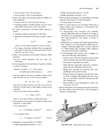
& Doubling number of baffles doubles velocity across . What is a Helixchanger heat exchanger? How does it
tube bundle and increase DP by four times. reduce fouling rates compared to conventional shell
. On what consideration maximum baffle spacing is and tube exchanger?
based? & A Helixchanger heat exchanger uses quadrant-
& Adequate support requirement for the tubes. shaped baffle plates that are arranged at an angle to
the tube axis in a sequential pattern, creating a helical
& Maximum unsupported tube span in inches is given
flow path through the tube bundle as shown in
by
Figure 10.30.
74d 0:75 ; ð10:7Þ & Baffle plates act as guide vanes rather than forming a
flow channel as in conventionally baffled heat ex-
where d is the outside diameter of tube, in inches.
changer. Uniformly higher flow velocities achieved
& For copper, aluminum, and their alloys, unsupported
in a Helixchanger heat exchanger offers enhanced
tube span is reduced by 12% (because tubes of these
convective heat transfer coefficients.
materials sag more easily).
& A well-designed Helixchanger heat exchanger in-
. What is the generally recommended minimum baffle
volves the following characteristics:
spacing?
➢ Uniform flow velocities through the tube bundle
& 0.3–0.5 (shell diameter). Not less than 2 in.
offering uniform film and metal temperatures.
(50.8 mm).
➢ Elimination of backflow and eddies.
. Give an equation for the estimation of number of baffles
➢ Shell side flow approaches plug flow conditions
in a heat exchanger.
improving the temperature driving force.
Number of baffles ¼ 10 tube length= ➢ Higher flow velocities are achieved with corre-
ð% baffle pitchÞðshell diameterÞ: ð10:8Þ spondingly lower pressure drops.
➢ Reduced shell size achieved with the Helixchan-
. Give the equations for space available for flow on the
ger heat exchanger offers higher tube side veloc-
shell side and free area of flow between baffles.
ities as a secondary benefit in reducing the tube
side fouling rates.
W ¼ D i ðd o T cl Þ; ð10:9Þ
➢ Helical baffles are recommended for fluids with
viscosities over 5 cP.
where W is the space for flow, D i is the I.D. of shell, d o
is the O.D. of tube, and T cl is the number of tubes across . What is the purpose of an impingement plate just below
centerline. the inlet nozzle on the shell side of a heat exchanger?
& Free area of flow between baffles,
Illustrate schematically.
A f ¼ WðB p 0:187Þ; ð10:10Þ
2
where A f is in inch and B p is baffle pitch, inch.
. Giveequations for calculation of number of tubes across
centerline of tube bundle.
& For square pitch,
0:5
T cl ¼ 1:19ðnumber of tubesÞ : ð10:11Þ
& For triangular pitch,
0:5
T cl ¼ 1:1ðnumber of tubesÞ : ð10:12Þ
. Summarize design guidelines for baffles.
& Baffle spacing/shell diameter ¼ 0.2–1. FIGURE 10.30 Helixchanger heat exchanger.