
Page 310 - Fluid mechanics, heat transfer, and mass transfer
P. 310
HEAT EXCHANGERS 291
. What are the considerations involved in fixing baffle
spacing?
& Baffle spacing is the most vital parameter in shell and
tube heat exchanger design.
& The TEMA standards specify the minimum baffle
spacing as one-fifth of the shell inside diameter or
5 cm (2 in.), whichever is greater.
& Closer spacing will result in poor bundle penetration
by the shell side fluid and difficulty in mechanically
cleaning the outside of the tubes.
& Low baffle spacing results in a poor stream
distribution.
& The maximum baffle spacing is the shell inside
diameter.
& Higher baffle spacing will lead to predominantly
FIGURE 10.27 Baffle cut orientations.
longitudinal flow, which is less efficient than cross
flow and large unsupported tube spans, which will
. Give examples when horizontal and vertical baffle cut make the exchanger prone to tube sagging and failure
orientations are used. due to flow-induced vibration.
& For single-phase fluids on the shell side, a horizontal . What is the recommended optimum baffle spacing?
baffle cut (Figure 10.27) is recommended, because & Optimum Baffle Spacing: For turbulent flow on the
this minimizes accumulation of deposits at the bot- shell side (N Re > 1000), the heat transfer coefficient
tom of the shell and also prevents stratification. varies 0.6–0.7 power of velocity.
& However, in the case of a two-pass shell (TEMA F), a & However, pressure drop varies 1.7–2.0 power.
vertical cut is preferred for ease of fabrication and & Forlaminarflow(N Re < 100),theexponentsare0.33for
bundle assembly. the heat transfer coefficient and 1.0 for pressure drop.
& For condensers and vaporizers, vertically cut baffles & Thus, as baffle spacing is reduced, pressure drop
are usually employed to enable condensed or vapor- increases at a much faster rate than does the heat
ized fluid to separate from the uncondensed vapor or transfer coefficient.
unvaporized liquid. & This means that there will be an optimum ratio of
& If the condensation or vaporization is in the shear
baffle spacing to shell inside diameter that will result
controlled regime, separation of phases will not in the highest efficiency of conversion of pressure
take place and horizontally cut baffles should be drop to heat transfer.
used.
& This optimum ratio is normally between 0.3 and 0.6.
& This is particularly true for partial condensers or
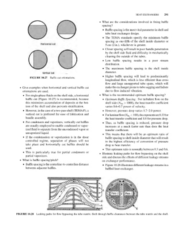
. Illustrate leaking paths for flow bypassing on the shell
partial vaporizers.
side and discuss the effects of different leakage streams
. What is baffle spacing/pitch?
on exchanger performance.
& Baffle spacing is the centerline-to-centerline distance & Figure 10.28 illustrates different leakage streams in a
between adjacent baffles. baffled heat exchanger.
Leaking paths for flow bypassing the tube matrix. Both through baffle clearances between the tube matrix and the shell.
FIGURE 10.28