
Page 314 - Fluid mechanics, heat transfer, and mass transfer
P. 314
HEAT EXCHANGERS 295
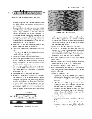
FIGURE 10.32 Rotating helical coil tube insert.
velocities. Secondary fluid motion is generated by the
tape twist, and the resulting twist mixing improves
heat transfer.
& Helical metal elements inside the tubes rotate making
use of the energy of the flowing fluid. This rotation
causes a high turbulence in the flow and thus
FIGURE 10.34 Wire mesh insert.
improves the internal heat transfer coefficient. As
the boundary layer is continuously renewed, the wall
temperature is lowered and fouling is reduced. By such as reflux condensers and thermosiphon reboi-
proper design and installation, rotating elements can lers. In all these applications, the boundary layer fluid
increase heat transfer coefficients by over 50% and is continuously displaced from the tube inner surface
reduce fouling to a significant effect. and remixed with the bulk fluid, thereby improving
& Applications include exchangers for crude oil pre- the convective heat transfer.
heating, petroleum products, and the like. & Figure 10.34 illustrates wire mesh tube insert.
& Figure 10.32 illustrates a typical rotating helical coil & The use of a full-length helically coiled insert can
insert. increase the swirl and pressure gradient in the radial
➢ The inserts are held in place by straight wires at direction. The boundary layer along the tube wall is
each end (inlet and outlet). thinner with the increase of radial swirl and pressure,
resulting in better heat flow through the fluid.
& Inserts are also used in U-bundle exchangers.
. What are the negative factors in the use of inserts in heat
& Some inserts operate with much lower shear than that
transfer tubes?
occurs in plain tubes. These allow fuller use of DP
& Inserts introduce tube cleaning problems and might
without resulting higher erosion problems when tube
cause plugging of the tubes with fouling fluids.
velocities are increased due to the insert.
& Some inserts introduce higher tube side DP.
& The inserts are used for fluids in the temperature
ranges of 200–350 C with flow velocities in the range . What is the important information that should be pro-
of 0.6–3 m/s. Tube sizes are between 12 and 50 mm vided to manufacturers of heat exchangers for proper
and lengths of 3–10 m. selection and sizing?
& Choice of Exchanger Type:
& Figure 10.33 illustrates twisted tape inserts.
➢ This directly affects process performance and also
& Wire matrix inserts tend to create well-distributed
flow conditions within individual tubes by continu- influences plant size and layout, the length of pipe
ously removing stagnant fluid from the tube wall and runs and the strength and size of supporting
replacing it with fluid from the center of the tubes. structures.
& In viscous, single-phase flow applications, wire ma- ➢ Other than shell and tube options such as plate
trix inserts are widely used to improve heat transfer exchangers, finned tube, and other compact and
characteristics. These devices have also been suc- microexchanger designs might be examined.
cessfully applied for two-phase flow applications, ➢ Enhancing features within the shell and tube
exchanger such as tube inserts, helical baffles,
twisted tubes, and rod baffles should also be
included in the consideration.
& Process Conditions:
➢ Maximum, minimum, and normal flows of process
fluids.
➢ Design pressure and maximum allowable DP.
➢ Heat duty expressed in terms of inlet and outlet
FIGURE 10.33 Twisted tape tube insert. temperatures and maximum deviations that can