
Page 311 - Fluid mechanics, heat transfer, and mass transfer
P. 311
SHELL AND TUBE HEAT EXCHANGERS
292
& On the shell side, there is not just one stream, as & From Table 10.4, it can be noticed that leakage and
inside tube side. There are many bypass and leakage bypass streams for laminar/viscous flow, the effects
streams that reduce the baffle effectiveness. are very high compared to turbulent flow conditions.
& Stream B is the main effective cross-flow stream, & Side strip baffles or the baffle tie rods are frequently
which can be related to flow across ideal tube banks. placed in the C and F stream paths to reduce the
& Stream A is the leakage stream in the orifice formed bypassing and force the fluid into the bundle.
by the clearance between the baffle tube hole and the & Pairs of seal strips, one pair for every 45 cm (18 in.) of
tube wall. shell internal diameter are used to ensure good shell
& Stream C is the tube bundle bypass stream that flows side cross-flow velocity and help reduce fluid flow
in the space between the outside of tube bundle and through the bypass area and reduce localized fouling
the inside of the shell wall. caused by low velocity.
& Stream E that leaks through the clearance between & These are typically 6.35 mm (1/4 in.) thick and
the baffle edge and shell wall. 10 mm (4 in.) wide.
& Stream F is the bypass stream in flow channel & Seal strips are set around the edge of the tube bundle
partitions due to omissions of tubes in tube pass and extend along the length of the tubes.
partitions. It occurs only in tube side multipass & They are inserted in grooves cut in the tube support
bundles and where the pass divider lane is oriented baffles.
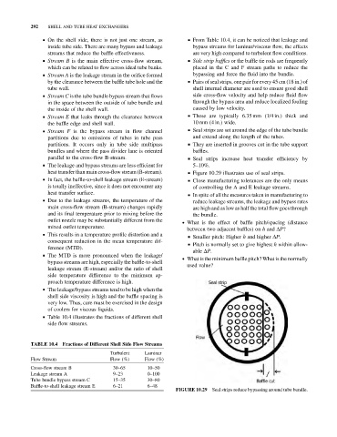
parallel to the cross-flow B-stream. & Seal strips increase heat transfer efficiency by
& The leakage and bypass streams are less efficient for 5–10%.
heat transfer than main cross-flow stream (B-stream). & Figure 10.29 illustrates use of seal strips.
& In fact, the baffle-to-shell leakage stream (E-stream) & Close manufacturing tolerances are the only means
is totally ineffective, since it does not encounter any of controlling the A and E leakage streams.
heat transfer surface. & In spite of all the measures taken in manufacturing to
& Due to the leakage streams, the temperature of the reduce leakage streams, the leakage and bypass rates
main cross-flow stream (B-stream) changes rapidly are high and as low as half the total flow goes through
and its final temperature prior to mixing before the the bundle.
outlet nozzle may be substantially different from the
. What is the effect of baffle pitch/spacing (distance
mixed outlet temperature.
between two adjacent baffles) on h and DP?
& This results in a temperature profile distortion and a
& Smaller pitch: Higher h and higher DP.
consequent reduction in the mean temperature dif-
& Pitch is normally set to give highest h within allow-
ference (MTD).
able DP.
& The MTD is more pronounced when the leakage/
. What is the minimum baffle pitch? What is the normally
bypass streams are high, especially the baffle-to-shell
used value?
leakage stream (E-stream) and/or the ratio of shell
side temperature difference to the minimum ap-
proach temperature difference is high.
& The leakage/bypass streams tend to be high when the
shell side viscosity is high and the baffle spacing is
very low. Thus, care must be exercised in the design
of coolers for viscous liquids.
& Table 10.4 illustrates the fractions of different shell
side flow streams.
TABLE 10.4 Fractions of Different Shell Side Flow Streams
Turbulent Laminar
Flow Stream Flow (%) Flow (%)
Cross-flow stream B 30–65 10–50
Leakage stream A 9–23 0–100
Tube bundle bypass stream C 15–35 30–80
Baffle-to-shell leakage stream E 6–21 6–48
Seal strips reduce bypassing around tube bundle.
FIGURE 10.29