
Page 309 - Fluid mechanics, heat transfer, and mass transfer
P. 309
SHELL AND TUBE HEAT EXCHANGERS
290
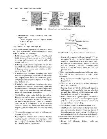
FIGURE 10.25 Effect of small and large baffle cuts.
➢ Disadvantage: Poorly distributed flow with
large eddies.
- Creates stagnant areas/dead spaces behind
baffles in the shell.
- Lower h.
(ii) Smaller Cut: High h and high DP.
. What are the considerations involved in deciding baffle
cut? What is the normally recommended percent range
of baffle cut in a heat exchanger? FIGURE 10.26 Large clearance between baffle and tube.
& Baffle cut canvary between 15% and 45% of the shell
& Instead of increasing baffle cut beyond 35% for
inside diameter. Maximum cut is 45% for single
decreasing DP, other aspects of tube bundlegeometry
segmental baffles so that every pair of baffles will
should be changed instead to achieve those goals.
support each tube.
For example, double segmental baffles or a divided
& Both very small and very large baffle cuts are det-
flow shell (TEMA J), or even a cross-flow shell
rimental to efficient heat transfer on the shell side due
(TEMA X), may be used to reduce the shell side
to large deviation from an ideal situation, as illus-
pressure drop.
trated in Figure 10.25.
. TEMA specifies clearances between baffles and tubes.
& If the baffle cut is very small, the main portion of the
What will be the consequences of using larger
flow acts as a jet through thewindow and then follows
clearances?
an S-shaped pattern across the tube bundle, gener-
& Large clearances result in fluid bypassing as shown in
ating large eddies of circulating fluid in the regions
Figure 10.26.
near the baffle tips.
& The tubes are to be inserted or withdrawn through
& If the baffle cut is very large, the main portion of the
baffle holes with ease.
stream bypasses the major portion of the bundle and
& Spacing should provide for differential expansion
flows between the baffle tips in virtually longitudinal
flow. Large eddies of recirculating fluid are created, and contraction between baffle plate and tubes that
which are inefficient for heat transfer. normally have different wall thicknesses and might
be of different materials of construction.
& The ideal flow pattern on the shell side is cross flow.
& Certain amount of leakage through the clearances is
However, the baffles that are needed to increase the
shell side velocity have the negative effect of altering to be permitted in order to reduce stagnant regions
the ideal cross-flow pattern. Therefore, a suitable and make turbulent conditions more uniform and
correction has to be employed to the heat transfer reduce shell side pressure drop.
coefficient for the ideal tube bundle. This correction & Such leakage reduces deposits in stagnant areas.
may be significant for very small and very large baffle & TEMA gives recommendations on the optimum clear-
cuts. ance requirements. Excessive bypassing occurs if
& The normally recommended range of baffle cuts are these clearances are large, resulting in fluid starving
between 20% and 25%. regionsintheshellwithlowfluidvelocitiesintheshell.
& Reducing baffle cut below 20% to increase the shell . Illustrate different orientations used for baffle cuts in a
side heat transfer coefficient or increasing the baffle shell and tube exchanger.
cut beyond 35% to decrease the shell side pressure & Figure 10.27 illustrates different baffle cut
drop usually leads to poor designs. orientations.