
Page 163 - Subyek Teknik Mesin - Forsthoffers Best Practice Handbook for Rotating Machinery by William E Forsthoffer
P. 163
Compressor Best Practices Be st Practice 3.7
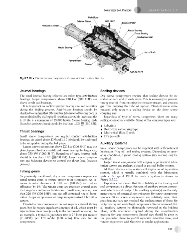
Fig 3.7.19 Flooded screw compressor (Courtesy of Kobelco e Kobe Steel Ltd)
Journal bearings Sealing devices
The usual journal bearing selected are roller type anti-friction Dry screw compressors require that sealing devices be in-
bearings. Larger compressors, above 220 kW (300 BHP) use stalled at each end of each rotor. This is necessary to prevent
sleeve or tilt pad bearings. timing gear oil from entering the process stream, and process
It is important to confirm proper bearing size and selection gas from entering the lube oil system. Flooded screw com-
during the bidding process. Anti-friction bearings should be pressors only require a sealing device on the drive screw
checked to confirm that DN number (diameter of bearing bore in coupling end.
mm multiplied by shaft speed) is within acceptable limits and the Regardless of type of screw compressor, there are many
L-10 life is a minimum of 25,000 hours. Sleeve bearing loads sealing alternatives available. Some of the common types are:
(based on projected area) should be less than 1,725 kN 2 (250 PSI).
m - Labyrinth
- Restrictive carbon ring type
Thrust bearings
- Mechanical (liquid) seals
Small screw compressors use angular contact anti-friction - Dry gas seals
bearings. As stated above, DN and L-10 life should be confirmed
to be acceptable during the bid phase. Auxiliary systems
Larger screw compressors above 220 kW (300 BHP) may use Small screw compressors can be supplied with self-contained
plain, tapered land or even tilt pad thrust bearings for larger size, lubrication (ring oil) and sealing systems. Depending on oper-
above 750 kW (1000 BHP). Regardless of type, bearing loads ating conditions, a jacket cooling system (dry screws) may be
should be less than 1,725 kN 2 (250 PSI). Larger screw compres-
m required.
sors use balancing devices to control the thrust load (balance Larger screw compressors will employ a pressurized lubri-
pistons).
cation system and perhaps a liquid or gas seal buffer system.
All flooded screw compressors will require an oil separation
Timing gears
system, which is usually combined with the lubrication
As previously mentioned, dry screw compressors require ex- system. A typical P&ID for such a system is shown in
ternal timing gears to ensure proper rotor clearances. An in- Figure 3.7.20.
crease in rotor clearance of 0.01 mm (0.0004") can reduce Experience has shown that the reliability of the bearing and
efficiency by 1%. The timing gears are precision-ground gears seal component is a direct function of auxiliary system compo-
that require continuous lubrication. Small compressors, less nent selection and design. The auxiliary system(s) are the only
than 220 kW (300 BHP), can use self-contained ring oil lubri- major source of potential cost reduction for screw compressor
cation. Larger compressors will require a pressurized lubrication vendors. Since screw compressors are relatively new, their
system. specifications have not reached the sophistication of those for
Flooded screw compressors do not require external timing reciprocating and centrifugal compressors. We recommend that
gears, but do require significant amounts of oil, which must be all auxiliary systems be thoroughly reviewed in the bidding
injected into the screws (usually in the bottom of the casing). As phase, with references required during the co-ordination
an example, a typical oil injection rate is 27 liters per minute meeting for large compressors. Special care should be given in
3
(7 GPM) per 170 m /hr (100 acfm) flow rate for air the pre-order phase to gas/oil separator retention time, and
compressors. vendor experience with this item in similar applications.
137