
Page 158 - Subyek Teknik Mesin - Forsthoffers Best Practice Handbook for Rotating Machinery by William E Forsthoffer
P. 158
Be st Practice 3 .7 Compressor Best Practices
Screw compressor types
Twin screw e oil-free (non oil-injected)
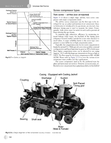
Figure 3.7.8 shows a single stage, oil-free, twin screw com-
pressor with major components noted.
The oil-free screw compressor was the first type to be de-
veloped for use as a plant and instrument air compressor. Since
no lubrication is introduced in the gas stream, an external, close
tolerance timing gear is used to separate the rotors. Conse-
quently, both screws must be sealed at each end to prevent oil
from entering the gas stream.
To maintain high volumetric efficiency by minimizing in-
ternal leakage (slip) losses, the backlash of the timing gears
(clearance between teeth) controls the screw rotor clearance to
small valves. A major reliability factor in dry screw type com-
pressors is rotor deflection at high compression ratios.
Typically, the compression ratio for dry screw compressors is
limited to around 5:1. With special screw rotor profiles, external
cooling jackets and liquid injection (as great as 20% of inlet mass
flow) higher compression ratios can be attained in one casing
(approx. 10:1) with discharge gas temperatures being as high as
550 F. The flow range for dry screw compressors is 300e40,000
Fig 3.7.7 Screw pv diagram ACFM. Please refer to Figure 3.7.9 to view the various screw
compressor rotor profiles and their applications.
Dry screw compressors used to be the preferred type for
plant and instrument air services. However, in recent years, oil-
flooded screw compressors have gained popularity in this field of
Fig 3.7.8 Single stage twin oil free compressor (Courtesy of Kobelco e Kobe Steel Ltd)
132