
Page 161 - Subyek Teknik Mesin - Forsthoffers Best Practice Handbook for Rotating Machinery by William E Forsthoffer
P. 161
Compressor Best Practices Be st Practice 3.7
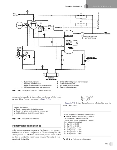
Fig 3.7.13 Oil separation system (Courtesy of Man/GHH)
K-1
action, unfortunately, is taken after installation of the com- T 2 P 2 ð K Þ
pressor. These facts are presented in Figure 3.7.14. T 1 ¼ P 1
Figure 3.7.15 defines the performance relationships used for
screw compressors.
In phase 1 of project:
Confirm compatibility of oil with process
Confirm oil will not be degraded by process gas
Visit installations to confirm vendor claims
Screw compressor performance relationships
3
CFM = (RPM) (DM ) (L/DM) (C 0 ) where:
Fig 3.7.14 Flooded screw reliability DM = male rotor diameter – inches
L/DM = length to diameter ratio of male rotor
C 0 = rotor profile constant
4 + 6 profile = 15.853
Performance relationships 3 + 4 profile = 18.082
4 + 6 ‘A’ profile = 17.17
All screw compressors are positive displacement compressors. 4 + 6 ‘D’ profile = 16.325
Performance of screw compressors is calculated using the adi- 3 + 4 ‘A’ profile = 19.372
abatic process. An adiabatic compression process assumes that 6 + 8 ‘D’ profile = 10.364
no heat is lost in the compression process. The path of com-
pression is defined by: Fig 3.7.15 Performance relationships
135