
Page 164 - Subyek Teknik Mesin - Forsthoffers Best Practice Handbook for Rotating Machinery by William E Forsthoffer
P. 164
Be st Practice 3 .7 Compressor Best Practices
Fig 3.7.20 Typical oil flooded screw oil
separation system (Courtesy of Kobelco e
Kobe Steel Ltd)
Capacity control in the valve, so cooling the recycled flow. This method of control
is the most efficient after the variable speed method.
Since screw compressors are positive displacement compres-
sors, their inlet volume flow is constant. If the speed of the rotor Bypass control
remains constant, like reciprocating compressors, various
methods are used to allow capacity to be varied. The four This method utilizes an external control valve to bypass excess
control methods used are presented in Figure 3.7.21. gas back to the suction. The recycled gas must be cooled. The
control of the bypass valve can be either pressure or flow. Bypass
control is the most inefficient method of capacity control.
Screw compressor capacity control methods:
Variable speed Selection guidelines
Suction throttling
Slide valve As previously mentioned, screw compressors have a flow range
3
Bypass of 170e68,000 m /hr (100e40,000 acfm) and can produce
compression ratios as high as 25:1. In order to optimize com-
pressor efficiency, accurate process data must be made available
Fig 3.7.21 Capacity control methods to the quoting vendors. The required input data is the same as
for other types of compressors, and is shown in Figure 3.7.24.
Variable speed It is most important to accurately define gas contaminants
As shown in the previous section, the capacity of the compressor (asphaltenes, etc.) and the percent per unit volume. Levels of
is a function of rotor profile and rotor speed. Variable speed is
the preferred method of capacity control for oil-free compres-
sors. It is not the preferred method for oil-flooded compressors,
since the levels of injection oil would have to be varied with
speed, and the slide valve method is available.
Suction throttling
Suction throttling enables the mass flow of the screw com-
pressor to be controlled by changing the inlet gas density. Care
must be used to ensure that the maximum compressor ratio is
not exceeded, since this could cause rotor deflection and/or
excessive discharge gas temperature.
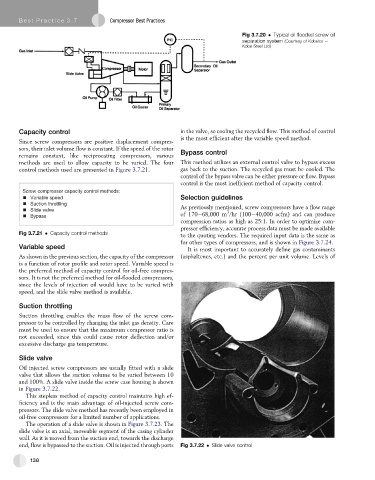
Slide valve
Oil injected screw compressors are usually fitted with a slide
valve that allows the suction volume to be varied between 10
and 100%. A slide valve inside the screw case housing is shown
in Figure 3.7.22.
This stepless method of capacity control maintains high ef-
ficiency and is the main advantage of oil-injected screw com-
pressors. The slide valve method has recently been employed in
oil-free compressors for a limited number of applications.
The operation of a slide valve is shown in Figure 3.7.23. The
slide valve is an axial, moveable segment of the casing cylinder
wall. As it is moved from the suction end, towards the discharge
end, flow is bypassed to the suction. Oil is injected through ports Fig 3.7.22 Slide valve control
138