
Page 162 - Subyek Teknik Mesin - Forsthoffers Best Practice Handbook for Rotating Machinery by William E Forsthoffer
P. 162
Be st Practice 3 .7 Compressor Best Practices
their function and monitor their condition. Screw compressors
are no exceptions. The five major component systems are:
k/k-1
T 2
P 2 =P 1 - Rotor
T 1
1/k - Journal bearing
T 2
V 2 =V 1 = - Thrust bearing
T 1
- Seals
where : P = PSIA
- Auxiliary systems
T= R
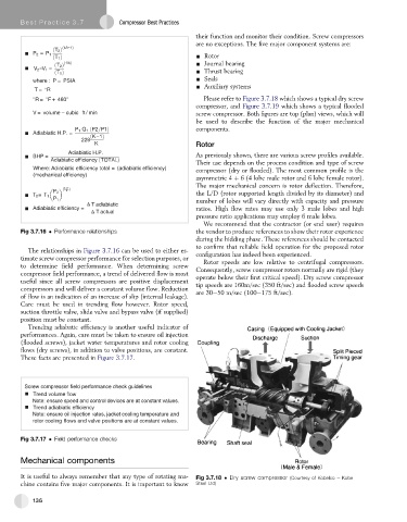
R= F + 460 Please refer to Figure 3.7.18 which shows a typical dry screw
compressor, and Figure 3.7.19 which shows a typical flooded
V = volume – cubic ft / min screw compressor. Both figures are top (plan) views, which will
be used to describe the function of the major mechanical
components.
Adiabiatic H.P. =
–
Rotor
Adiabiatic H.P.
BHP = As previously shown, there are various screw profiles available.
Adiabiatic efficiency TOTAL
Their use depends on the process condition and type of screw
Where: Adiabiatic efficiency total = (adiabiatic efficiency) compressor (dry or flooded). The most common profile is the
(mechanical efficiency)
asymmetric 4 þ 6 (4 lobe male rotor and 6 lobe female rotor).
The major mechanical concern is rotor deflection. Therefore,
k- 1
k
P 2 the L/D (rotor supported length divided by its diameter) and
T 2 =T 1
P 1 number of lobes will vary directly with capacity and pressure
T adiabiatic
Adiabiatic efficiency = ratios. High flow rates may use only 3 male lobes and high
T actual
pressure ratio applications may employ 6 male lobes.
We recommend that the contractor (or end user) requires
Fig 3.7.16 Performance relationships the vendor to produce references to show their rotor experience
during the bidding phase. These references should be contacted
to confirm that reliable field operation for the proposed rotor
The relationships in Figure 3.7.16 can be used to either es-
timate screw compressor performance for selection purposes, or configuration has indeed been experienced.
Rotor speeds are low relative to centrifugal compressors.
to determine field performance. When determining screw Consequently, screw compressor rotors normally are rigid (they
compressor field performance, a trend of delivered flow is most operate below their first critical speed). Dry screw compressor
useful since all screw compressors are positive displacement tip speeds are 160m/sec (350 ft/sec) and flooded screw speeds
compressors and will deliver a constant volume flow. Reduction are 30e50 m/sec (100e175 ft/sec).
of flow is an indication of an increase of slip (internal leakage).
Care must be used in trending flow however. Rotor speed,
suction throttle valve, slide valve and bypass valve (if supplied)
position must be constant.
Trending adiabatic efficiency is another useful indicator of
performances. Again, care must be taken to ensure oil injection
(flooded screws), jacket water temperatures and rotor cooling
flows (dry screws), in addition to valve positions, are constant.
These facts are presented in Figure 3.7.17.
Screw compressor field performance check guidelines
Trend volume flow
Note: ensure speed and control devices are at constant values.
Trend adiabiatic efficiency
Note: ensure oil injection rates, jacket cooling temperature and
rotor cooling flows and valve positions are at constant values.
Fig 3.7.17 Field performance checks
Mechanical components
It is useful to always remember that any type of rotating ma- Fig 3.7.18 Dry screw compressor (Courtesy of Kobelco e Kobe
chine contains five major components. It is important to know Steel Ltd)
136