
Page 465 - Subyek Teknik Mesin - Forsthoffers Best Practice Handbook for Rotating Machinery by William E Forsthoffer
P. 465
Be st Practice 7 .31 Lube, Seal and Control Oil System Best Practices
B.P. 7.31. Supporting Material
Accumulators
Referring to concepts previously discussed in this section, the
equivalent vessel concept exactly defines an accumulator func-
tion. An accumulator is simply a vessel which compensates for
rapid, short term flow disturbances in the auxiliary system. Most
accumulators contain bladders (see Figure 7.31.1). It is impor-
tant to remember that transient disturbances are on the order of
micro seconds and usually less than five seconds in duration.
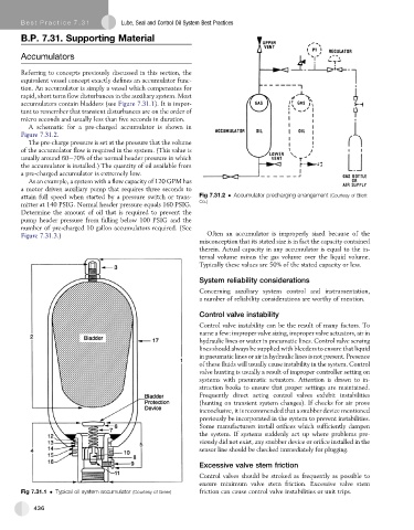
A schematic for a pre-charged accumulator is shown in
Figure 7.31.2.
The pre-charge pressure is set at the pressure that the volume
of the accumulator flow is required in the system. (This value is
usually around 60e70% of the normal header pressure in which
the accumulator is installed.) The quantity of oil available from
a pre-charged accumulator is extremely low.
As an example, a system with a flow capacity of 120 GPM has
a motor driven auxiliary pump that requires three seconds to
attain full speed when started by a pressure switch or trans- Fig 7.31.2 Accumulator precharging arrangement (Courtesy of Elliott
Co.)
mitter at 140 PSIG. Normal header pressure equals 160 PSIG.
Determine the amount of oil that is required to prevent the
pump header pressure from falling below 100 PSIG and the
number of pre-charged 10 gallon accumulators required. (See
Figure 7.31.3.) Often an accumulator is improperly sized because of the
misconception that its stated size is in fact the capacity contained
therein. Actual capacity in any accumulator is equal to the in-
ternal volume minus the gas volume over the liquid volume.
Typically these values are 50% of the stated capacity or less.
System reliability considerations
Concerning auxiliary system control and instrumentation,
a number of reliability considerations are worthy of mention.
Control valve instability
Control valve instability can be the result of many factors. To
name a few: improper valve sizing, improper valve actuators, air in
hydraulic lines or water in pneumatic lines. Control valve sensing
lines should always be supplied with bleeders to ensure that liquid
in pneumatic lines or air in hydraulic lines is not present. Presence
of these fluids will usually cause instability in the system. Control
valve hunting is usually a result of improper controller setting on
systems with pneumatic actuators. Attention is drawn to in-
struction books to ensure that proper settings are maintained.
Frequently direct acting control valves exhibit instabilities
(hunting on transient system changes). If checks for air prove
inconclusive, it is recommended that a snubber device mentioned
previously be incorporated in the system to prevent instabilities.
Some manufacturers install orifices which sufficiently dampen
the system. If systems suddenly act up where problems pre-
viously did not exist, any snubber device or orifice installed in the
sensor line should be checked immediately for plugging.
Excessive valve stem friction
Control valves should be stroked as frequently as possible to
ensure minimum valve stem friction. Excessive valve stem
Fig 7.31.1 Typical oil system accumulator (Courtesy of Greer) friction can cause control valve instabilities or unit trips.
436