
Page 462 - Subyek Teknik Mesin - Forsthoffers Best Practice Handbook for Rotating Machinery by William E Forsthoffer
P. 462
Lube, Seal and Control Oil System Best Practices Best Practice 7 .29
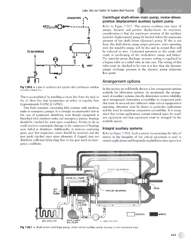
Centrifugal shaft-driven main pump, motor-driven
positive displacement auxiliary system pump
Refer to Figure 7.29.7.Thissystemcombinestwo typesof
pumps, dynamic and positive displacement. An important
consideration is that the maximum pressure of the auxiliary
(positive displacement) pump be limited below the maximum
pressure of the shaft-driven (dynamic) pump. If this is not
done, the shaft-driven pump output pressure, when operating
with the stand-by pump, will be less and its output flow will
be reduced to zero. Continued operation in this mode will
result in overheating of the shaft-driven pump and failure.
The stand-by pump discharge pressure setting is regulated by
a bypass valve or a relief valve in this case. The setting of this
valve must be checked to be sure it is less than the dynamic
pumps discharge pressure at the dynamic pump minimum
flow point.
Arrangement options
Fig 7.29.6 Lube oil rundown tank system with continuous overflow
(Courtesy of Elliott Co.) In this section we will briefly discuss a few arrangement options
available for lubrication systems. As mentioned, the arrange-
This is accomplished by installing a return line from the tank to ment of auxiliary systems directly determines system reliability
the oil drain line that incorporates an orifice to regulate flow since arrangement determines accessibility to component parts
(approximately 8 LPM [2 GPM]). that must be serviced and calibrated while critical equipment is
One final comment concerning lube systems with rundown operating. Attention must be drawn to particular applications
tanks or emergency pumps. It is strongly recommended that in and the need to maximize component accessibility. It is recog-
the case of equipment shutdown, even though equipment is nized that certain applications contain minimal space for auxil-
furnished with rundown tanks and emergency pumps, bearings iary equipment and that equipment must be arranged for the
should be checked for wear upon coastdown. Failure to do so available spaces.
could result in catastrophic damage to the equipment if bearings
were failed at shutdown. Additionally, in systems employing Integral auxiliary systems
gears, gear box inspection covers should be removed and the Refer to Figure 7.29.8. Such a system incorporating the lube oil
gear mesh checked since spray elements, if clogged, may not system in the baseplate of the critical equipment is used in
distribute sufficient lubricating flow to the gear mesh in emer- remote applications and frequently on platforms since space is at
gency conditions.
Fig 7.29.7 Shaft-driven centrifugal pump, motor-driven auxiliary pump (Courtesy of York International Corp.)
433