
Page 461 - Subyek Teknik Mesin - Forsthoffers Best Practice Handbook for Rotating Machinery by William E Forsthoffer
P. 461
Be st Practice 7 .29 Lube, Seal and Control Oil System Best Practices
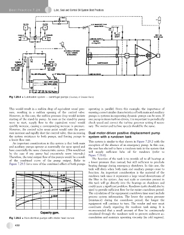
Fig 7.29.4 Lubrication system e centrifugal pumps (Courtesy of Dresser-Rand)
This would result in a sudden drop of equivalent vessel pres- operating in parallel. From this example, the importance of
sure, resulting in a sudden opening of the control valve. ensuring correct similar characteristics of both main and auxiliary
However, in this case, the sudden pressure drop would initiate pumps in systems incorporating dynamic pumps can be seen. If
starting of the stand-by pump. As soon as the stand-by pump one pump is steam turbine-driven, it is important to periodically
were to start, supply flow to the equivalent vessel would check speed and correct the turbine governor setting if neces-
quickly increase, causing a corresponding increase in pressure. sary. The motor and turbine speeds should be the same.
However, the control valve sense point would note the pres-
sure increase and rapidly shut the control valve, thus increasing Dual motor-driven positive displacement pump
the system resistance to both pumps, and forcing pumps to system with a rundown tank
a lower flow rate.
This system is similar to that shown in Figure 7.29.2 with the
An important consideration in this system is that both main exception of the absence of an emergency pump. In this case,
and auxiliary pumps operate at essentially the same speed and
the user has elected to have a rundown tank in the system that
have essentially the same characteristic curves. (This would not will supply sufficient lube oil for rundown (refer to
be the case if one pump had excessively worn internals.)
Therefore, the total output flow of the pumps would be a result Figure 7.29.6).
The function of the tank is to provide oil to all bearings at
of the combined curve of the pump output. Refer to
Figure 7.29.5 for a view of the combined effect of both pumps a lower pressure than normal, but still sufficient to preclude
bearing damage during emergency shutdown. In this case, the
tank will drain when both main and auxiliary pumps cease to
function. An important consideration is the material of the
rundown tank since it represents a large vessel downstream of
the filter in the system. Any rust scale or corrosion present in
this tank will go directly into the bearings on shutdown and
could cause a significant problem. Rundown tanks should also be
sized to provide sufficient flow for the entire coastdown period.
The calculation of the equipment coastdown time must include
process system information. The lower the system pressure
(resistance) during the coastdown period, the longer the
equipment will continue to turn. The vendor and user must
coordinate closely regarding the rundown tank sizing. It is
recommended that a small amount of flow be continuously
circulated through the rundown tank to prevent sediment ac-
Fig 7.29.5 Non-identical pumps with stable head curves cumulation and maintain operating viscosity (in cold regions).
432