
Page 466 - Subyek Teknik Mesin - Forsthoffers Best Practice Handbook for Rotating Machinery by William E Forsthoffer
P. 466
Lube, Seal and Control Oil System Best Practices Best Practice 7 .31
Control valve sensing lines
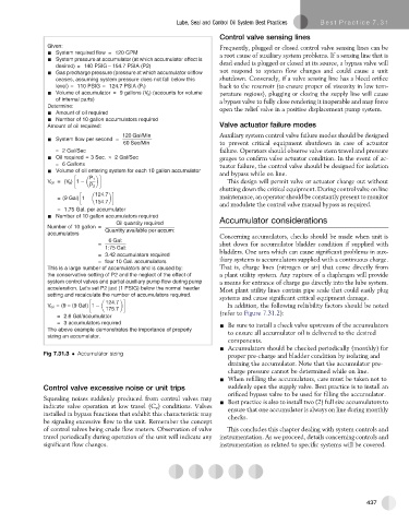
Given: Frequently, plugged or closed control valve sensing lines can be
System required flow = 120 GPM a root cause of auxiliary system problems. If a sensing line that is
System pressure at accumulator (at which accumulator effect is
desired) = 140 PSIG – 154.7 PSIA (P2) dead ended is plugged or closed at its source, a bypass valve will
Gas precharge pressure (pressure at which accumulator oilflow not respond to system flow changes and could cause a unit
ceases, assuming system pressure does not fall below this shutdown. Conversely, if a valve sensing line has a bleed orifice
level) = 110 PSIG = 124.7 PSIA (P 1 ) back to the reservoir (to ensure proper oil viscosity in low tem-
Volume of accumulator = 9 gallons (V a ) (accounts for volume perature regions), plugging or closing the supply line will cause
of internal parts) a bypass valve to fully close rendering it inoperable and may force
Determine: open the relief valve in a positive displacement pump system.
Amount of oil required
Number of 10 gallon accumulators required
Amount of oil required: Valve actuator failure modes
120 Gal/Min Auxiliary system control valve failure modes should be designed
System flow per second =
60 Sec/Min to prevent critical equipment shutdown in case of actuator
= 2 Gal/Sec failure. Operators should observe valve stem travel and pressure
Oil required = 3 Sec. 2 Gal/Sec gauges to confirm valve actuator condition. In the event of ac-
= 6 Gallons
tuator failure, the control valve should be designed for isolation
Volume of oil entering system for each 10 gallon accumulator
and bypass while on line.
V oil =(V a ) This design will permit valve or actuator change out without
shutting down the critical equipment. During control valve on line
= (9 Gal) maintenance, an operator should be constantly present to monitor
and modulate the control valve manual bypass as required.
= 1.75 Gal. per accumulator
Number of 10 gallon accumulators required
Oil quantity required Accumulator considerations
Number of 10 gallon =
Quantity available per accum:
accumulators
Concerning accumulators, checks should be made when unit is
6 Gal:
= shut down for accumulator bladder condition if supplied with
1:75 Gal:
bladders. One area which can cause significant problems in aux-
= 3.42 accumulators required
= four 10 Gal. accumulators iliary systems is accumulators supplied with a continuous charge.
This is a large number of accumulators and is caused by: That is, charge lines (nitrogen or air) that come directly from
the conservative setting of P2 and the neglect of the effect of a plant utility system. Any rupture of a diaphragm will provide
system control valves and partial auxiliary pump flow during pump a means for entrance of charge gas directly into the lube system.
acceleration. Let's set P2 just (1 PSIG) below the normal header Most plant utility lines contain pipe scale that could easily plug
setting and recalculate the number of accumulators required.
systems and cause significant critical equipment damage.
V oil = (9 = (9 Gal) In addition, the following reliability factors should be noted
(refer to Figure 7.31.2):
= 2.6 Gal/accumulator
= 3 accumulators required - Be sure to install a check valve upstream of the accumulators
The above example demonstrates the importance of properly
to ensure all accumulator oil is delivered to the desired
sizing an accumulator.
components.
- Accumulators should be checked periodically (monthly) for
Fig 7.31.3 Accumulator sizing proper pre-charge and bladder condition by isolating and
draining the accumulator. Note that the accumulator pre-
charge pressure cannot be determined while on line.
- When refilling the accumulators, care must be taken not to
Control valve excessive noise or unit trips suddenly open the supply valve. Best practice is to install an
orificed bypass valve to be used for filling the accumulator.
Squealing noises suddenly produced from control valves may - Best practice is also to install two (2) full size accumulators to
indicate valve operation at low travel (C v ) conditions. Valves ensure that one accumulator is always on line during monthly
installed in bypass functions that exhibit this characteristic may checks.
be signaling excessive flow to the unit. Remember the concept
of control valves being crude flow meters. Observation of valve This concludes this chapter dealing with system controls and
travel periodically during operation of the unit will indicate any instrumentation. As we proceed, details concerning controls and
significant flow changes. instrumentation as related to specific systems will be covered.
437