
Page 531 - Subyek Teknik Mesin - Forsthoffers Best Practice Handbook for Rotating Machinery by William E Forsthoffer
P. 531
Be st Practice 9 .1 Dry Gas Seal Best Practices
Best
Best Practice 9.1Practice 9.1Practice 9.1
Best
To ensure optimum safety and reliability of dry gas seal systems of low MTBF (less than 12 months) and large
systems, end users must be proactive in the project phase revenue losses.
or during seal system modifications to specify operating The following examples highlight omitted details in dry gas seal
parameters. specifications that have resulted in seal MTBFs of less than 12 months:
The main parameters fall into the following categories: Failure to identify the actual gas properties (sour gas, gas
All possible operating, start-up and upset conditions on the seal composition)
data sheet Failure to identify saturated seal gas conditions at start-up, upset or
Required system design details by incorporating all site, company and operating conditions
industry lessons learned into the project or revamp specification Failure to properly specify maximum flare header pressure
A detailed (P&ID) and data sheet to quoting machinery vendors that Failure to define the actual dew point of supplied nitrogen for
will completely specify system and component design intermediate and separation gas
Allowing the EP&C (contractor) and/or machinery vendor to design Failure to prohibit the use of orifices in the secondary vent resulting
the dry gas seal system will expose the plant to safety and reliability in seal pressure reversals
issues that cannot be known by other parties. Failure to specify oil sampling devices in the secondary seal vent
Following the guidelines completely in this best practice and port (sight glasses, valves or automatic drainers) leading to
requiring compliance with all specified details will ensure a safe and secondary seal oil contamination and eventual failure.
trouble-free system of the highest reliability.
Benchmarks
This best practice has been used since the late 1990s to specify dry
Lessons Learned gas seal system requirements during projects and for field modifica-
Failure to consider specific plant operating conditions and tions. This approach has resulted in dry gas seal systems of the highest
seal system lessons learned has resulted in dry gas seal safety levels and reliability (seal MTBFs greater than 90 months).
B.P. 9.1. Supporting Material
Dry gas seal (DGS) systems have been used for the past two
decades, and are specified by many end users as the seal of
choice for most compressor applications. One would therefore
think that seal and system designs are well-known and proven.
However, experience shows that failures are still quite
common. For instance, in 2007, FAI dealt with nearly 50 DGS
failures.
These failures raise several questions. Are they all caused by
‘foreign material’ contamination or ingestion? Are they
connected with improper seal selection or unreliable system
hardware? Who is responsible: seal vendors, compressor ven-
dors, or end users?
In reviewing DGS failures experienced in 2006 and previous
years, the conclusion was drawn that in the majority of cases, the
root cause is that the seal and system configuration were not
designed to handle all the actual site operating conditions, in-
cluding start-up, shut-down and upsets that should and could
have been anticipated.
The end user has the most complete knowledge of the pro-
cess and plant operating procedures. Therefore, he or she needs
to be proactive in terms of project DGS requirements, and
specify the type of seal and system most suited to the plant and
application, based on his or her knowledge and experience. Seal
and compressor vendor input and experience are obviously
required, but neglecting to evaluate the proposed system in
detail against all operating modes subjects the user to the risk of
unacceptable downtime and revenue losses, particularly in the
‘mega plants’ being built today.
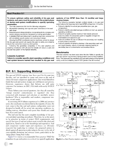
Figure 9.1.1 shows a recommended ‘best practice’ P&ID for
a tandem dry gas seal system in a critical (un-spared) application Fig 9.1.1 Best Practice tandem seal P&ID
502