
Page 534 - Subyek Teknik Mesin - Forsthoffers Best Practice Handbook for Rotating Machinery by William E Forsthoffer
P. 534
Dry Gas Seal Best Practices Be st Practice 9.1
possibility of toxic of flammable gas leaks out of the system. This retrofitted easily, can be modified to minimize outward gas
will be discussed in detail below. leakage and optimize safety and reliability.
Possible oil ingestion from the lube system e asuitablesep-
aration seal must be provided to eliminate the possibility of oil Dry gas seal design
ingestion from the bearings. Whenever a gas seal system is
utilized, the design of the critical equipment by definition
incorporates a separate lube oil and seal system. Consideration Principles of operation
must be given during the design or retrofit phases to the sep- The intention of this sub-section is to present the principles of
aration between the liquid (lube) and gas seal system. operation of a dry gas seal in a conceptual form. The reader is
‘O’ ring (secondary seal components) design and maintenance e directed to any of the good literature available on this subject for
most seal vendors state that ‘O’ ring life is limited, and they a detailed review of gas seal design.
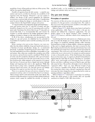
should be changed every five years for operating seals as well as Refer to Figure 9.1.5, which shows a mechanical seal used in
spare seals. Experience has shown that dry gas ‘O’ ring seals can pump applications, while Figure 9.1.6 shows a dry gas me-
exceed this limit. It is recommended that seal vendors be chanical seal utilized for compressor applications. The seal
required to provide references for similar applications prior to designs appear to be almost identical. Close attention to
making a decision to change out the seals after five years. Figure 9.1.6, however, will show reliefs of the rotating face of
If all of the above considerations are incorporated in the the seal.
design of a gas seal system, its reliability has the potential to Considering that both seals operate on a fluid may give some
exceed that of a liquid seal system and the operating costs can be hint as to why the designs are so very similar. The objective of
reduced. seal design is to positively minimize leakage while removing
Before moving to the next section, however, one must con- frictional heat, in order to obtain reliable, continuous operation
sider that the relative reliability of gas and liquid seal systems is of the seal. In a liquid application, the heat is removed by the
a function of proper specification, design, etc. as mentioned fluid which passes between the rotating and stationary faces and
previously. A properly designed liquid seal system that is oper- the seal flush and changes from a liquid to gaseous state (heat of
ated and maintained can achieve reliabilities comparable to a gas vaporization). This is precisely why all seals are said to leak and
seal system. Also, when one considers the operating costs of the explains the recent movement in the industry to seal-less pumps
two systems, various factors must be considered. While the loss in toxic or flammable service. If the fluid between the rotating
of costly seal oil is positively eliminated, with a gas seal system faces now becomes a gas, its capacity to absorb frictional heat is
(assuming oil ingestion from the lube system does not occur) the significantly less than that of a liquid. Therefore an ‘equivalent
loss of process gas, while minimal, can be expensive. It is argued orifice’ must continuously exist between the faces to reduce
that the loss of process gas from a liquid seal system through friction and allow a sufficient amount of fluid to pass and thus
drainer and degassing tank vents is also significant. While this take away the heat. The problem obviously is how to obtain this
may be true in many cases, a properly specified, designed and ‘equivalent orifice’. There are many different designs of gas
operated liquid seal system can minimize process gas leakage seals. However, regardless of the design, the dynamic action of
such that it is equal or even less than that of a gas seal. the rotating face must create a dynamic opening force that will
There is no question that gas seal systems contain far fewer overcome the static closing forces acting on the seal to create an
components and are easier to maintain than liquid seal systems. opening and hence ‘equivalent orifice’.
These systems will be used extensively in the years ahead. The Refer to Figure 9.1.7 which shows a typical gas dry seal face.
intention of this discussion is to point out that existing liquid seal Notice the spiral grooves in this picture; they are typically
systems which cannot be justified for retrofit, or cannot be machined at a depth of 100e400 micro inches.
Fig 9.1.5 Typical pump single mechanical seal
505