
Page 537 - Subyek Teknik Mesin - Forsthoffers Best Practice Handbook for Rotating Machinery by William E Forsthoffer
P. 537
Be st Practice 9 .1 Dry Gas Seal Best Practices
suction. It must be noted, however, that this port is next to the the disaster bushing. Most designs still incorporate a disaster
journal bearing. Therefore a means of positively preventing bushing between the backup seal and the bearing cavity, known
entry of lube oil into this port must be provided in order to these days as the barrier seal. Attention in this design must be
prevent the loss of lube oil or prevent the ingestion of lube oil given to control of the inter-stage pressure between the primary
into the compressor if this line is referenced back to the com- and backup seal. Experience has shown that low differentials
pressor suction. A suitable design must be incorporated for this across the backup seal can significantly decrease its life. As in the
bushing. Typically called a disaster bushing, it serves the dual case of liquid seals, a minimum pressure in the cavity between
purpose of isolating the lube system from the seal system, and the seals of 172e207 kPa (25e30 psi) is usually specified. This
providing a means of minimizing the leakage of process fluid into is achieved by properly sizing the orifice in the vent or reference
the lube system in the event of a gas seal failure. In this system, line back to the suction to ensure this pressure is maintained. All
a pressure switch upstream of an orifice in a vent line is used as instrumentation and filtration are identical to that of the pre-
an alarm and a shutdown to monitor flow. This switch uses the vious system.
concept of an equivalent vessel in that increased seal leakage will
increase the rate of supply versus demand flow in the equivalent Dual seal and system options for toxic and/or
vessel (pipe) and result in a higher pressure. When a high flow is flammable gas applications
reached, the orifice and pressure switch setting are thus sized
and selected to alarm and shut down the unit if necessary. As in There are many field-proven options which are currently avail-
any system, close attention to changes in operating parameters is able for use in toxic and/or flammable gas applications. In this
required. Flow meters must be properly sized and kept clean, so section we will discuss the following systems:
that relative changes in the flows can be detected in order to - Tandem seals for dry gas applications
adequately plan for seal maintenance. - Tandem seals for saturated gas applications
- Tandem seals with interstage labyrinth and nitrogen
High pressure applications separation gas
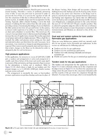
In this application, for pressures in excess of 6,895 kPa (1,000 - Double seal system for dry gas or saturated gas applications
psi), a tandem seal arrangement or series seal arrangement is
usually used. Since failure of the inner seal would cause signif- Tandem seals for dry gas applications
icant upset of the seal system, and large amounts of gas to escape
to the atmosphere, a backup seal is employed. Refer to The tandem seal arrangement for this application is shown in
Figure 9.1.10, which shows a triple dry gas tandem seal. For Figure 9.1.11 and a schematic of this seal in the compressor seal
present designs up to 17,250 kPa (2500 psi), double tandem housing is shown in Figure 9.1.12. Gas from the compressor dis-
seals are proven and used. charge enters the port closest to the compressor (labyrinth end)
The arrangement is essentially the same as low/medium and the majority of the gas enters the compressor through this
pressure applications except that a backup seal is used in place of labyrinth. To ensure that process gas, which is not treated by the
Fig 9.1.10 Dry gas seal: a triple tandem dry gas seal arrangement (Courtesy of Dresser-Rand Corp.)
508