
Page 536 - Subyek Teknik Mesin - Forsthoffers Best Practice Handbook for Rotating Machinery by William E Forsthoffer
P. 536
Dry Gas Seal Best Practices Be st Practice 9.1
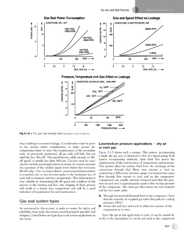
Fig 9.1.9 Dry gas seal leakage rates (Courtesy of John Crane Co.)
thus resulting in excessive leakage. Consideration must be given Low/medium pressure applications e dry air
to the system under consideration, to tailor system de- or inert gas
compression times to meet the requirements of the secondary
Figure 9.1.3 shows such a system. This system, incorporating
seals. As previously mentioned, all gas seals will leak, but not
until the face ‘lifts off’. This speed known, oddly enough, as ‘lift- a single dry gas seal, is identical to that of a liquid pump flush
off speed’ is usually less than 500 rpm. Caution must be exer- system incorporating relatively clean fluid that meets the
cised in variable speed applications to ensure the system prevents requirements of the seal in terms of temperature and pressure.
the operation of the variable speed driver below this minimum This system takes the motive fluid from the discharge of the
lift-off value. One recommendation concerning instrumentation compressor through dual filters (ten microns or less) in-
is to provide one or two thermocouples in the stationary face of corporating a differential pressure gauge and proportions equal
each seal to measure seal face temperature. This information is flow through flow meters to each seal on the compressor.
very valuable in determining lift-off speed and condition of the Compressors are usually pressure balanced such that the pres-
sure on each end is approximately equal to the suction pressure
grooves in the rotating seal face. Any clogging of these grooves
will result in a higher face temperature and will be a good of the compressor. The clean gas then enters the seal chamber
and has two main paths:
indication of requirement for seal maintenance.
A. Through the internal labyrinth back to the compressor. Note
that the majority of supplied gas takes this path for cooling
Gas seal system types
purposes (99%).
B. Across the seal face and back to either the suction of the
As mentioned in this section, in order to ensure the safety and compressor or to vent.
reliability of gas seals, the system must be properly specified and
designed. Listed below are typical gas seal system applications in Since the gas in this application is inert, it can be vented di-
use today. rectly to the atmosphere or can be put back to the compressor
507