
Page 532 - Subyek Teknik Mesin - Forsthoffers Best Practice Handbook for Rotating Machinery by William E Forsthoffer
P. 532
Dry Gas Seal Best Practices Be st Practice 9.1
used in a large plant of high daily revenue (greater than $1 MM/ compressor were retrofitted for a gas seal. WOW! What a dif-
day). ference. Why are there such a small number of components for
The reliability of critical equipment is dependent on the re- the gas seal system? As an aid, refer to Figure 9.1.4, which shows
liability of each component in every auxiliary system connected a typical pump liquid flush system as specified by the American
with the critical equipment unit. How do we maximize critical Petroleum Institute. This system incorporates a liquid me-
equipment reliability? The easiest way is to eliminate the aux- chanical seal and utilizes pump discharge liquid as a flush for the
iliary systems. Imagine the opportunity to eliminate all of the seal. Refer now to Figure 9.1.3 and observe the similarities. It
components; pumps, filters, reservoirs, etc. and thereby increase should be evident that a gas seal system is simplified in com-
reliability and hopefully, the safety of the equipment. The gas pressor applications over a liquid seal system, merely because
seal as used in compressor applications affords the opportunity the gas seal utilizes the process fluid. This is exactly the same
to achieve these objectives. However, the gas seal is still part of case for a pump. By using the process fluid, and not a liquid, one
a system and the entire gas seal system must be properly spec- can eliminate the need to separate liquid from a gas, thereby
ified, designed, maintained and operated to achieve the objec- totally eliminating the need for a liquid supply system and the
tives of optimum safety and reliability of the critical equipment. need for a contaminated liquid (sour oil) drain system.
In this section, the principles of gas seal design will be Referring back to Figure 9.1.2, therefore, we can see that the
discussed and applied to various gas seal system types. In addi- following major components are eliminated:
tion, best practices will be discussed for saturated gas systems as
well as shutdown philosophies. 1. The seal oil reservoir
2. The pumping units
3. The exchangers
System function 4. The temperature control valves
5. The overhead tank
The function of a gas seal system is naturally the same as a liquid 6. The drain pot
seal system. The function of a fluid seal system, remembering that 7. The degassing tank
a fluid can be a liquid or a gas, is to continuously supply clean fluid 8. All control valves
to each specified seal interface point at the required differential 9. A significant amount of instrumentation
pressure, temperature, and flow rate. Therefore, one would Referring back to the function definition of the gas seal system,
expect the design of a gas seal and a liquid seal to be very similar, all requirements are met. ‘Continuously supplying fluid’ is
which, in fact, they are. Then why are their systems so different?
achieved by utilizing the discharge pressure of the compressor.
The requirements for ‘specified differential pressure, tempera-
Comparison of a liquid and gas sealing system ture and flow rate’ are met by the design of the seal itself, which
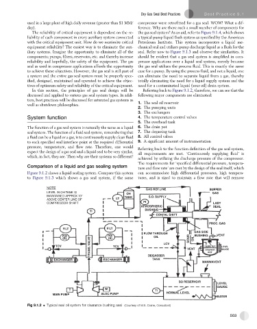
Figure 9.1.2 shows a liquid sealing system. Compare this system can accommodate high differential pressures, high tempera-
to Figure 9.1.3 which shows a gas seal system, if the same tures, and is sized to maintain a flow rate that will remove
NOTE GAS REF.LINE BUFFER
LEVEL IN OH TANK IS OH GAS
MAINTAINED APPROX 10° TANK S.O. SUPPLY
ABOVE CENTER LINE OF LT
COMPRESSOR SHAFT PI LABY
ATMOSPHERIC SEAL
BUSHING
TI
CONFAL SHIFT
PROC. GAS
FILT FILT
GAS SIDE
FLOW THROUGH
PDI PDI OIL BUSHING VENT
TRANS. VALVE VENT DEMISTER GAUGE
(S) (S) SOUR OIL
TCV TCV LCV
LEVEL
DRAINER
POT
TANK
EXCHANGER EXCHANGER DEGASSER
MANWAVENT
SO RESERVOIR
LEVEL
GAUGE
T M TI
MAIN PUMP ALDC PUMP NORMAL LEVEL
HEATER
Fig 9.1.2 Typical seal oil system for clearance bushing seal (Courtesy of M.E. Crane, Consultant)
503