
Page 535 - Subyek Teknik Mesin - Forsthoffers Best Practice Handbook for Rotating Machinery by William E Forsthoffer
P. 535
Be st Practice 9 .1 Dry Gas Seal Best Practices
Fig 9.1.6 Typical design for curved face e spiral groove non-
contact seal; curvature may alternately be on rotor (Courtesy of John Crane
Co.)
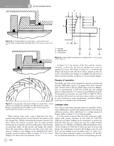
Fig 9.1.8 Hydrostatic force balance on seal stator (F C ¼ F O ) (Courtesy
of John Crane Co.)
In Figure 9.1.7, the rotation of the face must be counter-
clockwise, to force the gas into the passages and create an
opening (F o ) force. This design is known as a ‘uni-directional’
design and requires that the faces always operate in this di-
rection. Alternative face designs are available that all rotate in
either direction and they are known as ‘bi-directional’ designs.
Ranges of operation
Essentially, gas seals can be designed to operate at speeds and
pressure differentials equal to or greater than those of liquid
seals. Present state-of-the-art (2010) limits seal face differen-
tials to approximately 17,250 kPa (2,500 psi) and rubbing
speeds to approximately 122 meters/second (400 feet/second).
Temperatures of operation can reach 538 C (1,000 F). Where
the seal face differential exceeds these values, seals can be used
in series (tandem) to meet specifications, provided sufficient
axial space is available in the seal housing.
Fig 9.1.7 Dry gas seal. Top: typical design for curved face e spiral Leakage rates
groove non-contact seal; curvature may alternately be on rotor;
Bottom: Typical spiral groove pattern on face of seal typical non- Since the gas seal when operating forms an equivalent orifice,
contact gas seal (Courtesy of John Crane Co.) whose differential is equal to the supply pressure minus the seal
reference pressure, there will always be a certain amount of
leakage. Refer to Figure 9.1.9 for leakage graphs.
When rotating, these vanes create a high head, low flow, It can be stated in general that, for most compressor appli-
impeller that pumps gas into the area between the stationary and cations with suction pressures of the order of 3,450 kPa
the rotating face, thereby increasing the pressure between the (500 psi) and below, leakage can be maintained at around one
faces. When this pressure is greater than the static pressure standard cubic foot per minute per seal. For a high pressure
holding the faces together, the faces will separate, thus forming application (17,250 kPa or 2,500 psi), differential leakage values
3
an equivalent orifice. In this specific seal design, the annulus can be as high as 8.5 Nm /hr (5 scfm) per seal. As in any seal
below the vanes forms a tight face such that under static (sta- design, the total leakage is equal to the leakage across the seal
tionary) conditions, zero leakage can be obtained if the seal is faces and any leakage across secondary seals (‘O’ rings, etc.).
properly pressure-balanced. Refer to Figure 9.1.8 for a force There have been reported incidences of explosive ‘O’ ring fail-
diagram that shows how this operation occurs. ure on rapid decompression of systems incorporating gas seals,
506