
Page 106 - T. Anderson-Fracture Mechanics - Fundamentals and Applns.-CRC (2005)
P. 106
1656_C02.fm Page 86 Thursday, April 14, 2005 6:28 PM
86 Fracture Mechanics: Fundamentals and Applications
2.12 INTERACTION OF MULTIPLE CRACKS
The local stress field and crack driving force for a given flaw can be significantly affected by the
presence of one or more neighboring cracks. Depending on the relative orientation of the neighboring
cracks, the interaction can either magnify or diminish the stress intensity factor. An example of the
former is an infinite array of coplanar cracks (Figure 2.21). The K solution for this configuration is
I
given by Equation (2.45) and is plotted in Figure 2.22. When cracks are parallel to one another, K I
tends to decrease due to the interaction. The interaction of both coplanar and parallel cracks is
discussed further in the following section.
2.12.1 COPLANAR CRACKS
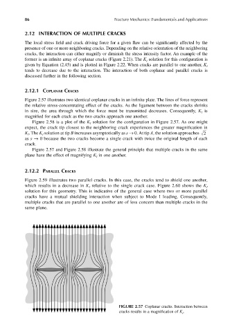
Figure 2.57 illustrates two identical coplanar cracks in an infinite plate. The lines of force represent
the relative stress-concentrating effect of the cracks. As the ligament between the cracks shrinks
in size, the area through which the force must be transmitted decreases. Consequently, K is
I
magnified for each crack as the two cracks approach one another.
Figure 2.58 is a plot of the K solution for the configuration in Figure 2.57. As one might
I
expect, the crack tip closest to the neighboring crack experiences the greater magnification in
K I . The K solution at tip B increases asymptotically as s → 0. At tip A, the solution approaches 2
I
as s → 0 because the two cracks become a single crack with twice the original length of each
crack.
Figure 2.57 and Figure 2.58 illustrate the general principle that multiple cracks in the same
plane have the effect of magnifying K in one another.
I
2.12.2 PARALLEL CRACKS
Figure 2.59 illustrates two parallel cracks. In this case, the cracks tend to shield one another,
which results in a decrease in K relative to the single crack case. Figure 2.60 shows the K I
I
solution for this geometry. This is indicative of the general case where two or more parallel
cracks have a mutual shielding interaction when subject to Mode I loading. Consequently,
multiple cracks that are parallel to one another are of less concern than multiple cracks in the
same plane.
FIGURE 2.57 Coplanar cracks. Interaction between
cracks results in a magnification of K I .