Page 103 - T. Anderson-Fracture Mechanics - Fundamentals and Applns.-CRC (2005)
P. 103

1656_C02.fm  Page 83  Thursday, April 14, 2005  6:28 PM


                       Linear Elastic Fracture Mechanics                                            83


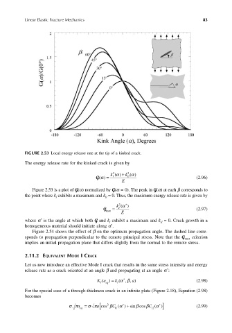
                       FIGURE 2.53 Local energy release rate at the tip of a kinked crack.
                       The energy release rate for the kinked crack is given by

                                                            k  2 () + k  α  2  ()
                                                                     α
                                                     G() =   I     I  I                          (2.96)
                                                       α
                                                                 E
                          Figure 2.53 is a plot of G(α) normalized by G(α = 0). The peak in G(α) at each β corresponds to
                       the point where k  exhibits a maximum and k  = 0. Thus, the maximum energy release rate is given by
                                    I
                                                         II
                                                              k  2 (α ∗ )
                                                         G   =  I                                (2.97)
                                                          max   E
                             *
                       where α  is the angle at which both G and k  exhibit a maximum and k  = 0. Crack growth in a
                                                           I
                                                                                 II
                                                            *
                       homogeneous material should initiate along α .
                          Figure 2.54 shows the effect of β on the optimum propagation angle. The dashed line corre-
                       sponds to propagation perpendicular to the remote principal stress. Note that the G max  criterion
                       implies an initial propagation plane that differs slightly from the normal to the remote stress.
                       2.11.2 EQUIVALENT MODE I CRACK

                       Let us now introduce an effective Mode I crack that results in the same stress intensity and energy
                                                                                    *
                       release rate as a crack oriented at an angle β and propagating at an angle α :
                                                                 ∗
                                                      Ka ) =  k (αβ  a , )                       (2.98)
                                                                  ,
                                                        (
                                                          q
                                                       I
                                                               I
                                                          e
                       For the special case of a through-thickness crack in an infinite plate (Figure 2.18), Equation (2.98)
                       becomes
                                          σπ a  eq  σπ [  a =  2 β C  11 ( α +  ∗  )  β cos β C sin  12 ( α ] cos  ∗  )  (2.99)
   98   99   100   101   102   103   104   105   106   107   108