
Page 98 - T. Anderson-Fracture Mechanics - Fundamentals and Applns.-CRC (2005)
P. 98
1656_C02.fm Page 78 Thursday, April 14, 2005 6:28 PM
78 Fracture Mechanics: Fundamentals and Applications
Fracture toughness specimens that fail by cleavage fracture usually do not form shear lips, so
the trends in Figure 2.43 and Figure 2.44 do not apply to such data. Cleavage fracture toughness
does exhibit a slight thickness-dependence due to weakest-link sampling effects. See Section 5.2
for a detailed discussion of this fracture mechanism.
2.10.3 PLASTIC ZONE EFFECTS
Section 2.9 outlines the conditions required for K-controlled fractures. The plastic zone must be
embedded within an elastic singularity zone in order for K to characterize crack-tip conditions.
Traditionally, the loss of K dominance with plastic zone growth has been lumped together with the
purported transition from “plane strain fracture” to “plane stress fracture,” as if these phenomena
were synonymous. In fact, there is not a direct correspondence between the plastic zone size and
the existence (or absence) of plane strain conditions near the crack tip. Three-dimensional elastic-
plastic finite element analyses of standard laboratory fracture toughness specimens have shown
that a high degree of triaxiality near the crack tip exists even when the entire cross-section has
yielded. Although K is not valid as a characterizing parameter under fully plastic conditions, a
single-parameter description of fracture toughness is still possible using the J integral, or crack-
tip-opening displacement (Chapter 3).
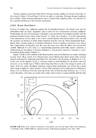
Figure 2.48 shows the evolution of the Mode I plastic zone at mid-thickness in a plate containing
an edge crack. These results were obtained from a three-dimensional elastic-plastic finite element
analysis performed by Nakamura and Parks [32]. The plastic zone boundary is defined at σ = σ YS
e
in this case. As the quantity (K I /σ Y S ) 2 increases relative to plate thickness B, the plastic zone size
increases, as one would expect. What is interesting about these results is the change in plastic zone
shape. At low K values, the plastic zone has a typical plane strain shape, but evolves into a plane
I
stress shape at higher K values (Figure 2.34(a)). This transition can be understood by referring to
I
Figure 2.42. At distances from the crack tip on the order of half the plate thickness, σ = 0. As a
zz
result, the plastic zone takes on a plane stress shape when it grows to approximately half the plate
FIGURE 2.48 Effect of K I , relative to thickness, of the plastic zone size and shape. Taken from Nakamura,
T. and Parks, D.M., ASME AMD-91. American Society of Mechanical Engineers, New York, 1988.