
Page 96 - T. Anderson-Fracture Mechanics - Fundamentals and Applns.-CRC (2005)
P. 96
1656_C02.fm Page 76 Thursday, April 14, 2005 6:28 PM
76 Fracture Mechanics: Fundamentals and Applications
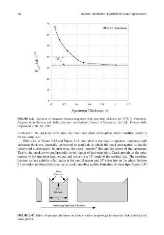
FIGURE 2.44 Variation of measured fracture toughness with specimen thickness for 7075-T6 Aluminum.
Adapted from Barsom and Rolfe, Fracture and Fatigue Control in Structur es. 2nd Ed., Prentice-Hall,
Englewood Cliffs, NJ, 1987.
is related to the crack-tip stress state, the traditional plane stress–plane strain transition model is
far too simplistic.
Plots such as Figure 2.43 and Figure 2.44, that show a decrease in apparent toughness with
specimen thickness, generally correspond to materials in which the crack propagation is ductile
(microvoid coalescence). In such tests, the crack “tunnels” through the center of the specimen.
That is, the crack grows preferentially in the region of high triaxiality. Crack growth on the outer
regions of the specimen lags behind, and occurs at a 45° angle to the applied load. The resulting
fracture surface exhibits a flat region in the central region and 45° shear lips on the edges. Section
5.1 provides additional information on crack tunneling and the formation of shear lips. Figure 2.45
FIGURE 2.45 Effect of specimen thickness on fracture surface morphology for materials that exhibit ductile
crack growth.