
Page 92 - T. Anderson-Fracture Mechanics - Fundamentals and Applns.-CRC (2005)
P. 92
1656_C02.fm Page 72 Thursday, April 14, 2005 6:28 PM
72 Fracture Mechanics: Fundamentals and Applications
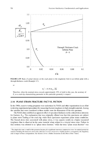
FIGURE 2.39 Ratio of actual stresses on the crack plane to the singularity limit in an infinite plate with a
through-thickness crack (Example 2.7).
or
K I * . Y S π a = 035σ
Therefore, when the nominal stress exceeds approximately 35% of yield in this case, the accuracy of
K I as a crack-tip–characterizing parameter in this particular geometry is suspect. 1
2.10 PLANE STRAIN FRACTURE: FACT VS. FICTION
In the 1960s, massive testing programs were undertaken by NASA and other organizations in an effort
to develop experimental procedures for measuring fracture toughness in high strength materials. Among
the variables that were considered in these studies were the dimensions of the test specimen.
The NASA data exhibited an apparent effect of specimen thickness on the critical stress intensity
for fracture, K . The explanation that was originally offered was that thin specimens are subject
crit
to plane stress loading at the crack tip, while thick specimens experience plane strain conditions.
The biaxial stress state associated with plane stress, it was argued, results in a higher measured
toughness than is observed in the same material when subject to a triaxial stress state. Failure in
thin sections was referred to as “plane stress fracture,” while the term “plane strain fracture” was
1 The singularity zone is small in this geometry because of a significant transverse compressive stress. In cracked geometries
loaded in bending, this transverse stress (also called the T stress) is near zero or slightly positive; consequently, the singularity
zone is larger in these configurations. See Section 3.6 for a further discussion on the effect of the T stress.