
Page 90 - T. Anderson-Fracture Mechanics - Fundamentals and Applns.-CRC (2005)
P. 90
1656_C02.fm Page 70 Thursday, April 14, 2005 6:28 PM
70 Fracture Mechanics: Fundamentals and Applications
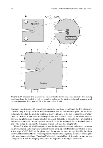
FIGURE 2.37 Schematic test specimen and structure loaded to the same stress intensity. The crack-tip
conditions should be identical in both configurations as long as the plastic zone is small compared to all
relevant dimensions. Thus, both will fail at the same critical K value.
boundary conditions, i.e., K characterizes crack-tip conditions even though the 1 r singularity
I
does not apply to the plastic zone. Since the structure and test specimen in Figure 2.37 are loaded
to the same K value, the crack-tip conditions must be identical in the two configurations. Further-
I
more, as the load is increased, both configurations will fail at the same critical stress intensity,
provided the plastic zone remains small in each case. Similarly, if both structures are loaded in
fatigue at the same ∆K, the crack-growth rates will be similar as long as the cyclic plastic zone is
embedded within the singularity-dominated zone in each case (see Chapter 10).
Figure 2.38 schematically illustrates the stress distributions in the structure and test specimen from
the previous figure. In the singularity-dominated zone, a log-log plot of the stress distribution is linear
with a slope of −1/2. Inside of the plastic zone, the stresses are lower than predicted by the elastic
solution, but are identical for the two configurations. Outside of the singularity-dominated zone, higher-
order terms become significant (Equation (2.36)) and the stress fields are different for the structure and
test specimen. K does not uniquely characterize the magnitude of the higher-order terms.