
Page 91 - T. Anderson-Fracture Mechanics - Fundamentals and Applns.-CRC (2005)
P. 91
1656_C02.fm Page 71 Thursday, April 14, 2005 6:28 PM
Linear Elastic Fracture Mechanics 71
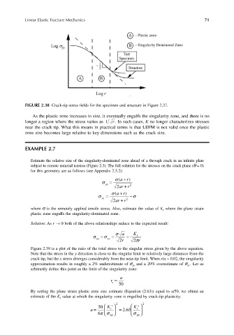
FIGURE 2.38 Crack-tip stress fields for the specimen and structure in Figure 2.37.
As the plastic zone increases in size, it eventually engulfs the singularity zone, and there is no
longer a region where the stress varies as 1 r . In such cases, K no longer characterizes stresses
near the crack tip. What this means in practical terms is that LEFM is not valid once the plastic
zone size becomes large relative to key dimensions such as the crack size.
EXAMPLE 2.7
Estimate the relative size of the singularity-dominated zone ahead of a through crack in an infinite plate
subject to remote uniaxial tension (Figure 2.3). The full solution for the stresses on the crack plane (θ = 0)
for this geometry are as follows (see Appendix 2.3.2):
σ = σ ar+( )
yy
+
2 ar r 2
σ xx = σ ar+( ) − σ
+
2 ar r 2
where σ is the remotely applied tensile stress. Also, estimate the value of K I where the plane strain
plastic zone engulfs the singularity-dominated zone.
Solution: As r → 0 both of the above relationships reduce to the expected result:
σ a K
σ σ = = = I
xx
yy
r 2 2 πr
Figure 2.39 is a plot of the ratio of the total stress to the singular stress given by the above equation.
Note that the stress in the y direction is close to the singular limit to relatively large distances from the
crack tip, but the x stress diverges considerably from the near-tip limit. When r/a = 0.02, the singularity
approximation results in roughly a 2% underestimate of σ yy and a 20% overestimate of σ xx . Let us
arbitrarily define this point as the limit of the singularity zone:
a
r ≈
s
50
By setting the plane strain plastic zone size estimate (Equation (2.63)) equal to a/50, we obtain an
estimate of the K I value at which the singularity zone is engulfed by crack-tip plasticity:
a = 50 K I ∗ 2 = 265 K I ∗ 2
.
6πσ YS σ YS
