
Page 93 - T. Anderson-Fracture Mechanics - Fundamentals and Applns.-CRC (2005)
P. 93
1656_C02.fm Page 73 Thursday, April 14, 2005 6:28 PM
Linear Elastic Fracture Mechanics 73
applied to toughness tests on thick sections. This two-dimensional viewpoint, which is still prevalent
in textbooks and published literature, is simplistic and misleading.
Much of the classical fracture mechanics theory is predicated on two-dimensional approxima-
tions. For example, the relationship between K and energy release rate (Equation (2.56)) is
I
rigorously correct only for the special cases of plane stress and plane strain. There are cases where
a two-dimensional model is appropriate, but there are other instances where a two-dimensional
outlook gives a distorted view of reality. The relationship between specimen dimensions and
apparent fracture toughness is an example of the latter.
In the 1960s, when “plane stress fracture” and “plane strain fracture” mechanisms were first
postulated, a detailed three-dimensional analysis of the stress state in front of a crack was simply
not possible. Today, three-dimensional finite element analyses of components with cracks are
commonplace (Chapter 12). Advances in computer technology have significantly aided in our
understanding of the behavior of material at the tip of a crack.
This section presents an updated perspective on the interrelationship between specimen dimen-
sions, crack-tip triaxiality, and fracture toughness.
2.10.1 CRACK-TIP TRIAXIALITY
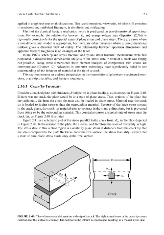
Consider a cracked plate with thickness B subject to in-plane loading, as illustrated in Figure 2.40.
If there was no crack, the plate would be in a state of plane stress. Thus, regions of the plate that
are sufficiently far from the crack tip must also be loaded in plane stress. Material near the crack
tip is loaded to higher stresses than the surrounding material. Because of the large stress normal
to the crack plane, the crack-tip material tries to contract in the x and z directions, but is prevented
from doing so by the surrounding material. This constraint causes a triaxial state of stress near the
crack-tip, as Figure 2.40 illustrates.
Figure 2.41 is a schematic plot of the stress parallel to the crack front, σ , in the plate depicted
zz
in Figure 2.40. In the interior of the plate, the z stress, and therefore the level of triaxiality, is high.
The stress state in this central region is essentially plane strain at distances from the crack tip that
are small compared to the plate thickness. Near the free surface, the stress triaxiality is lower, but
a state of pure plane stress exists only at the free surface.
FIGURE 2.40 Three-dimensional deformation at the tip of a crack. The high normal stress at the crack tip causes
material near the surface to contract, but material in the interior is constrained, resulting in a triaxial stress state.