
Page 99 - T. Anderson-Fracture Mechanics - Fundamentals and Applns.-CRC (2005)
P. 99
1656_C02.fm Page 79 Thursday, April 14, 2005 6:28 PM
Linear Elastic Fracture Mechanics 79
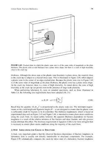
FIGURE 2.49 Cracked plate in which the plastic zone size is of the same order of magnitude as the plate
thickness. The plastic zone at mid thickness has a plane stress shape, but there is a zone of high triaxiality
close to the crack tip.
thickness. Although the stress state at the plastic zone boundary is plane stress, the material close
to the crack tip is subject to a triaxial stress state. This is illustrated in Figure 2.49, which depicts
a plastic zone in the center of an edge-cracked plate. Because the plastic zone size in Figure 2.49
is of the same order of magnitude as the plate thickness, the plastic zone has a plane stress shape.
At the crack tip, however, there is a zone of high triaxiality. As stated above, the zone of high
triaxiality at the crack tip can persist even in the presence of large-scale plasticity.
When performing laboratory K tests on standard specimens, such as those illustrated in
Ic
Table 2.4, the following size requirements have been adopted [30, 31]:
K 2
aB W − ( a) ≥ . 25 σ YS (2.88)
Ic
,,
Recall that the quantity (K I /σ Y S ) 2 is proportional to the plastic zone size. The minimum require-
ments on the crack length and ligament length (W – a) are designed to ensure that the plastic zone
is sufficiently small for fracture to be K-controlled. The thickness requirement, which is based on
experimental data such as Figure 2.43 and Figure 2.44, is intended to ensure plane strain conditions
along the crack front. As stated earlier, however, the apparent thickness dependence in fracture
toughness is a result of the relative mixtures of flat fracture and shear fracture, and side grooves
would eliminate this effect. The thickness requirement in Equation (2.88) is far more stringent than
is necessary to ensure plane strain conditions along the majority of the crack front.
2.10.4 IMPLICATIONS FOR CRACKS IN STRUCTURES
A final, very important point is that the observed thickness dependence of fracture toughness in
laboratory tests is usually not directly transferable to structural components. For example,
Figure 2.50 schematically compares the crack-tip stress state of a laboratory fracture toughness