
Page 101 - T. Anderson-Fracture Mechanics - Fundamentals and Applns.-CRC (2005)
P. 101
1656_C02.fm Page 81 Thursday, April 14, 2005 6:28 PM
Linear Elastic Fracture Mechanics 81
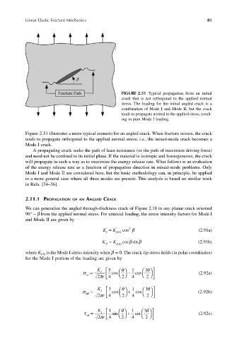
FIGURE 2.51 Typical propagation from an initial
crack that is not orthogonal to the applied normal
stress. The loading for the initial angled crack is a
combination of Mode I and Mode II, but the crack
tends to propagate normal to the applied stress, result-
ing in pure Mode I loading.
Figure 2.51 illustrates a more typical scenario for an angled crack. When fracture occurs, the crack
tends to propagate orthogonal to the applied normal stress; i.e., the mixed-mode crack becomes a
Mode I crack.
A propagating crack seeks the path of least resistance (or the path of maximum driving force)
and need not be confined to its initial plane. If the material is isotropic and homogeneous, the crack
will propagate in such a way as to maximize the energy release rate. What follows is an evaluation
of the energy release rate as a function of propagation direction in mixed-mode problems. Only
Mode I and Mode II are considered here, but the basic methodology can, in principle, be applied
to a more general case where all three modes are present. This analysis is based on similar work
in Refs. [34–36].
2.11.1 PROPAGATION OF AN ANGLED CRACK
We can generalize the angled through-thickness crack of Figure 2.18 to any planar crack oriented
90° − β from the applied normal stress. For uniaxial loading, the stress intensity factors for Mode I
and Mode II are given by
K I K = I () cos β (2.91a)
2
0
β
K II K = I() 0 cos sinβ (2.91b)
where K is the Mode I stress intensity when β = 0. The crack-tip stress fields (in polar coordinates)
I(0)
for the Mode I portion of the loading are given by
σ = I 5 cos θ K − 1 cos 3 θ (2.92a)
rr
2 πr 4 4 2
2
σ = I 3 cos θ K + 1 cos 3 θ (2.92b)
θθ
r
2
2 π 4 4 2
τ = I 1 sin θ K + 1 sin 3 θ (2.92c)
θ r
2 πr 4 4 2
2