
Page 102 - T. Anderson-Fracture Mechanics - Fundamentals and Applns.-CRC (2005)
P. 102
1656_C02.fm Page 82 Thursday, April 14, 2005 6:28 PM
82 Fracture Mechanics: Fundamentals and Applications
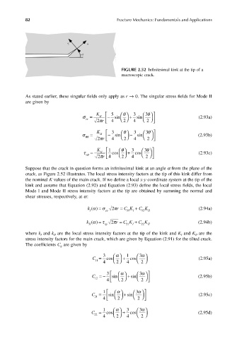
FIGURE 2.52 Infinitesimal kink at the tip of a
macroscopic crack.
As stated earlier, these singular fields only apply as r → 0. The singular stress fields for Mode II
are given by
K θ 5 3 3 θ
σ = II − sin + sin (2.93a)
rr
2
2 πr 4 4 2
K θ 3 3 3 θ
σ = II − sin − sin (2.93b)
r
θθ
2
2 π 4 4 2
τ = II 1 cos θ K + 3 cos 3 θ (2.93c)
θ r
2
2 πr 4 4 2
Suppose that the crack in question forms an infinitesimal kink at an angle α from the plane of the
crack, as Figure 2.52 illustrates. The local stress intensity factors at the tip of this kink differ from
the nominal K values of the main crack. If we define a local x-y coordinate system at the tip of the
kink and assume that Equation (2.92) and Equation (2.93) define the local stress fields, the local
Mode I and Mode II stress intensity factors at the tip are obtained by summing the normal and
shear stresses, respectively, at α:
k I y y r () = C α 11 Kσ I + C π 2 12 K = I I (2.94a)
k II xy r () = C α 21 Kτ I + C π 2 22 K = II (2.94b)
where k and k are the local stress intensity factors at the tip of the kink and K and K are the
I
II
II
I
stress intensity factors for the main crack, which are given by Equation (2.91) for the tilted crack.
The coefficients C are given by
ij
α
C = 3 cos + 1 cos α 3 (2.95a)
11 2 2
4 4
3 α 3
α
C =− sin + sin (2.95b)
12 4 2 2
1 α 3
α
C = sin + sin (2.95c)
21 4 2 2
α
C = 1 cos + 3 cos α 3 (2.95d)
22 2 2
4 4