
Page 169 - T. Anderson-Fracture Mechanics - Fundamentals and Applns.-CRC (2005)
P. 169
1656_C003.fm Page 149 Monday, May 23, 2005 5:42 PM
Elastic-Plastic Fracture Mechanics 149
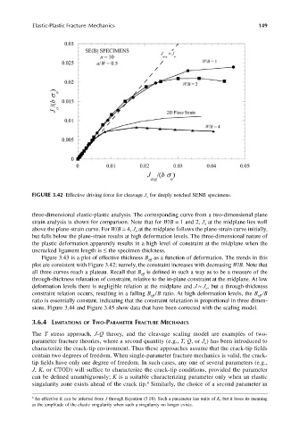
FIGURE 3.42 Effective driving force for cleavage J o for deeply notched SENB specimens.
three-dimensional elastic-plastic analysis. The corresponding curve from a two-dimensional plane
strain analysis is shown for comparison. Note that for W/B = 1 and 2, J at the midplane lies well
o
above the plane-strain curve. For W/B = 4, J at the midplane follows the plane-strain curve initially,
o
but falls below the plane-strain results at high deformation levels. The three-dimensional nature of
the plastic deformation apparently results in a high level of constraint at the midplane when the
uncracked ligament length is ≤ the specimen thickness.
Figure 3.43 is a plot of effective thickness B as a function of deformation. The trends in this
eff
plot are consistent with Figure 3.42; namely, the constraint increases with decreasing W/B. Note that
all three curves reach a plateau. Recall that B is defined in such a way as to be a measure of the
eff
through-thickness relaxation of constraint, relative to the in-plane constraint at the midplane. At low
deformation levels there is negligible relation at the midplane and J ≈ J , but a through-thickness
o
constraint relation occurs, resulting in a falling B /B ratio. At high deformation levels, the B /B
eff
eff
ratio is essentially constant, indicating that the constraint relaxation is proportional in three dimen-
sions. Figure 3.44 and Figure 3.45 show data that have been corrected with the scaling model.
3.6.4 LIMITATIONS OF TWO-PARAMETER FRACTURE MECHANICS
The T stress approach, J-Q theory, and the cleavage scaling model are examples of two-
parameter fracture theories, where a second quantity (e.g., T, Q, or J ) has been introduced to
o
characterize the crack-tip environment. Thus these approaches assume that the crack-tip fields
contain two degrees of freedom. When single-parameter fracture mechanics is valid, the crack-
tip fields have only one degree of freedom. In such cases, any one of several parameters (e.g.,
J, K, or CTOD) will suffice to characterize the crack-tip conditions, provided the parameter
can be defined unambiguously; K is a suitable characterizing parameter only when an elastic
8
singularity zone exists ahead of the crack tip. Similarly, the choice of a second parameter in
8 An effective K can be inferred from J through Equation (3.18). Such a parameter has units of K, but it loses its meaning
as the amplitude of the elastic singularity when such a singularity no longer exists.