
Page 34 - T. Anderson-Fracture Mechanics - Fundamentals and Applns.-CRC (2005)
P. 34
1656_C01.fm Page 14 Tuesday, April 12, 2005 5:55 PM
14 Fracture Mechanics: Fundamentals and Applications
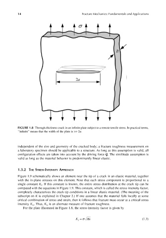
FIGURE 1.8 Through-thickness crack in an infinite plate subject to a remote tensile stress. In practical terms,
‘‘infinite” means that the width of the plate is >> 2a.
independent of the size and geometry of the cracked body; a fracture toughness measurement on
a laboratory specimen should be applicable to a structure. As long as this assumption is valid, all
configuration effects are taken into account by the driving force G. The similitude assumption is
valid as long as the material behavior is predominantly linear elastic.
1.3.2 THE STRESS-INTENSITY APPROACH
Figure 1.9 schematically shows an element near the tip of a crack in an elastic material, together
with the in-plane stresses on this element. Note that each stress component is proportional to a
single constant K . If this constant is known, the entire stress distribution at the crack tip can be
I
computed with the equations in Figure 1.9. This constant, which is called the stress-intensity factor,
completely characterizes the crack-tip conditions in a linear elastic material. (The meaning of the
subscript on K is explained in Chapter 2.) If one assumes that the material fails locally at some
critical combination of stress and strain, then it follows that fracture must occur at a critical stress
intensity K . Thus, K is an alternate measure of fracture toughness.
Ic
Ic
For the plate illustrated in Figure 1.8, the stress-intensity factor is given by
K I a = σπ (1.3)