
Page 35 - T. Anderson-Fracture Mechanics - Fundamentals and Applns.-CRC (2005)
P. 35
1656_C01.fm Page 15 Tuesday, April 12, 2005 5:55 PM
History and Overview 15
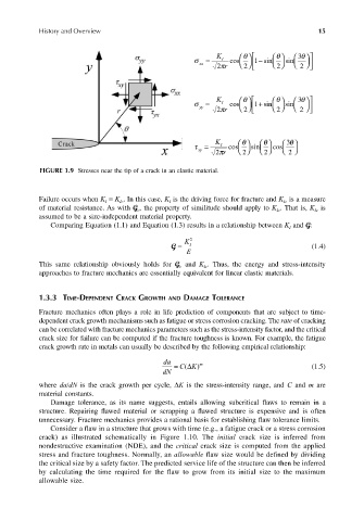
σ xx = I cos θ K 1 − sin θ sin 3 θ
2
2 πr 2
2
σ = I cos θ K 1 + sin θ sin 3 θ
yy
2 πr 2
2
2
K θ θ 3 θ
τ = I cos sin cos
xy
2
2
2 πr 2
FIGURE 1.9 Stresses near the tip of a crack in an elastic material.
Failure occurs when K = K . In this case, K is the driving force for fracture and K is a measure
I
Ic
I
Ic
of material resistance. As with G , the property of similitude should apply to K . That is, K is
c
Ic
Ic
assumed to be a size-independent material property.
Comparing Equation (1.1) and Equation (1.3) results in a relationship between K and G:
I
K 2
G = I (1.4)
E
This same relationship obviously holds for G and K . Thus, the energy and stress-intensity
c
Ic
approaches to fracture mechanics are essentially equivalent for linear elastic materials.
1.3.3 TIME-DEPENDENT CRACK GROWTH AND DAMAGE TOLERANCE
Fracture mechanics often plays a role in life prediction of components that are subject to time-
dependent crack growth mechanisms such as fatigue or stress corrosion cracking. The rate of cracking
can be correlated with fracture mechanics parameters such as the stress-intensity factor, and the critical
crack size for failure can be computed if the fracture toughness is known. For example, the fatigue
crack growth rate in metals can usually be described by the following empirical relationship:
da m
CK)∆
dN = ( (1.5)
where da/dN is the crack growth per cycle, ∆K is the stress-intensity range, and C and m are
material constants.
Damage tolerance, as its name suggests, entails allowing subcritical flaws to remain in a
structure. Repairing flawed material or scrapping a flawed structure is expensive and is often
unnecessary. Fracture mechanics provides a rational basis for establishing flaw tolerance limits.
Consider a flaw in a structure that grows with time (e.g., a fatigue crack or a stress corrosion
crack) as illustrated schematically in Figure 1.10. The initial crack size is inferred from
nondestructive examination (NDE), and the critical crack size is computed from the applied
stress and fracture toughness. Normally, an allowable flaw size would be defined by dividing
the critical size by a safety factor. The predicted service life of the structure can then be inferred
by calculating the time required for the flaw to grow from its initial size to the maximum
allowable size.