
Page 61 - From Smart Grid to Internet of Energy
P. 61
Introduction to smart grid and internet of energy systems Chapter 1 47
steady-state performance evaluation quantities such as total vector error, fre-
quency error, and rate of change of frequency error as discussed earlier. The
featured technology of PMU differs from conventional SCADA system in terms
of timing, synchronization, and reliability where PMU can provide more than
60 samples at each cycle while SCADA can only provide 4 samples utmost for
each cycle. Moreover, PMU samples frequency and ROCOF data in addition to
voltage and current phasors [4, 7].
It is noted that the first PMU was developed by Virginia Tech complying
with initial standard that have been approved in 1992. The recent PMUs are
more accurate and can acquire different type of phasors from power network
and substations. Some commercial PMUs are integrated with protection and
detection equipments such as relays, circuit breakers, fault detection devices
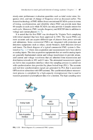
and timers. The block diagram of a typical commercial PMU system is illus-
trated in Fig. 1.13 where data acquisition and measurements have been shown
as analog inputs. The data acquisition equipments that are used in analog inputs
are generally fundamental current and voltage transformers to provide attenu-
ated current and voltage waveforms that are inherited from transmission and
distribution networks in MV and kV rates. The attenuated measurement signals
are fed to data acquisition interface where the sampling process is carried out
with synchronization data provided by phase locked loop (PLL). The accurate
and real time synchronization signals are generated by PLL that is associated
GPS receiver subsection with GPS antenna. The synchronized phasor measure-
ment process is completed by a high-capacity microprocessor that is used to
transmit generated synchrophasor data over a modem. The high sampling rates
FIG. 1.13 Block diagram of a commercial PMU system.