Page 269 - Fundamentals of Gas Shale Reservoirs
P. 269

GAS FLOW IN MICROPORES AND NANOPORES  249
            recently for tight gas systems (with pores of 1–10 µm in   where
            size). Brown et al. (1946) added to our understanding of
            these processes and articulated the concept of slip flow,                   kT    ,             (11.3)
                                                                                         B
            which provided an explanation for the observed relationship                 2  2  p
            between gas‐flow rate and mean pressure.
              As explained earlier, the pores in producing shale gas   in which k  is the Boltzmann constant (1.3805 × 10  J/K), T
                                                                                                         −23
            reservoirs are in the range of 1–100s nm; the gas molecules   is temperature (K), p is pressure (pa), and δ is the collision
                                                                         B
            contained in the pores are of comparable size (~0.5 nm),   diameter of the gas molecule (m). Table 11.1 presents flow
            and under certain pressure and temperature conditions the   regimes corresponding to Knudsen number ranges.
            distance between gas molecules (mean free path) exceeds   Continuum no‐slip flow or Darcy equation is valid for
            the size of the pores. In such conditions, the gas molecules   K  < 10 . Continuum flow with slip correction (Klinkenberg)
                                                                      −3
                                                                  n
            might move singly through the pores and the concept of   is valid for K  < 10 , which covers most conventional gas
                                                                                −1
                                                                            n
            continuum and bulk flow may not be applicable. Knudsen   reservoirs and many tight gas reservoir conditions as well.
            number (K ) is the ratio of mean free path (λ) to pore diam-
                     n                                           However, because of the existence of nanopores in a shale
            eter (d), and can be used to identify different flow regimes.
                                                                 system, K  could be larger than 0.1, and hence new forms of
                                                                        n
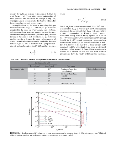
                                                                 gas‐flow equations are needed. Figure 11.6 presents Knudsen
                                 K n   ,               (11.2)    number  as  a  function  of  pore  size  and  mean  reservoir
                                     d                           pressure, and shows the validity of different flow equations.
            TAbLE 11.1  Validity of different flow equations as functions of Knudsen number
                                      Knudsen number (K )
                                                    n
                                 Lower bound    Upper bound             Flow regime
            Shale gas reservoirs     0              10 −3        Continuum/Darcy flow        Navier–Stokes equation
                                                                   (no‐slip flow)
                                    10 −3           10 −2        Slip flow (Klinkenberg
                                    10 −2           10 −1          model)
                                    10 −1           10 0         Transition flow
                                    10 0            10 1
                                    10 1            ∞            Free‐molecule flow


                                      10 1

                                      10 0

                                      10 –1


                                      10 –2
                                    K R
                                 Shale gas   10 –3


                                      10 –4     d = 1 nm                                     Klinkenberg equation
                                                d = 10 nm
                                                d = 100 nm                               Darcy equation
                                      10 –5     d = 1  m
                                                d = 10  m
                                      10 –6
                                        10 –1          10 0           10 1           10 2
                                                            p m  (MPa)
            FIGURE 11.6  Knudsen number (K ) as function of mean reservoir pressure for porous system with different mean pore size. Validity of
                                       n
            different gas‐flow equations and condition corresponding to shale gas reservoirs are marked.
   264   265   266   267   268   269   270   271   272   273   274