
Page 389 - Fundamentals of Gas Shale Reservoirs
P. 389
DEVELOPMENT PHASE DISCUSSION 369
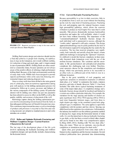
Reservoir navigation-precise wellbore plcement 17.5.6 Current Hydraulic Fracturing Practices
(Azimuthal resistivity and gamma images)
Because permeability is so low in shale reservoirs, little to
no production from a well can occur without first breaking
up the rock by some kind of fracturing process. Fracturing
the rock and propping open the induced fractures creates
high permeability pathways, which allows the reservoir
formation to produce at much higher flow rates than it could
naturally. This process dramatically increases hydrocarbon
production and makes the well profitable, where it would
not have been without fracturing. The importance of the
“customized/optimized” hydraulic fracture design for
each individual well is paramount to success, although the
“cookie‐cutter” approach is still quite common. This design
FIGURE 17.5 Reservoir navigation to stay in the zone and the approach/methodology may be partly justified by the lack of
sweet spot (Source: Baker Hughes). the information required for designing the frac and/or by the
economics. The fact that reservoir properties vary signifi-
cantly, both vertically and aerially along the lateral, creates
additional challenges in designing the “optimum” treatment.
Drilling fluid system design and selection should involve It is difficult to model the fracture complexity in these natu-
a fluid that achieves (i) proper hole cleaning, (ii) stabiliza- rally fractured shale formations even with the use of the
tion of clays in the formation, (iii) overall wellbore stability, modern fracture simulators. The variations and the uncer-
(iv) reduction of drag and stuck pipe, and (v) improvement tainty in the geomechanical and petrophysical properties
in rate of penetration (ROP). Drilling fluids are often consid- complicate this challenging task even further. Therefore,
ered as commodity items, because operators are not always some operators choose for the completion and stimulation
aware of the positive effects of utilizing a high‐performance design, which was previously proven to be successful in
drilling fluid. Because of the high environmental sensitivity an offset well, in a different part of the field or even in a
of many shale wells, WBMs have been designed to provide different formation.
superior performance while at the same time lowering envi- Due to the great variability of rock properties and
ronmental impact and reducing disposal costs. significant variations in stimulation treatments of different
Since so many wells have been drilled in the same general shale plays, it is “unfair” to summarize the trends, common
area of a shale play, there are numerous opportunities during practices, and rules of thumb. However, Table 17.1 has been
post well analysis (of the drilling optimization process) for included. The table shows typical fracturing treatments of
constructive follow‐up to assess successes and failures of some of the major shale plays. A completion strategy and a
the various components of the drilling system. Of particular hydraulic fracture design should be localized and limited to
interest will be drilling runs where one just one parameter a certain area within a particular shale play. For example, the
has been altered to assess its effect on the ROP as well as the variations for the stage spacing and number of clusters are
quality, stability, and accuracy of placement of the well. quite significant: from 150 to 750 ft spacing (250 to 350 ft is
Knowledge capture during the drilling optimization pro- used most frequently) between stages, and from three to
cess involves documenting lessons learned from the field, so eight clusters per stage, in the cemented (cased hole) plug‐
that subsequent drilling runs will benefit from previous ones. and‐perf type of completion. The same applies to open‐hole
This continuous improvement becomes a cycle as knowledge completions with the packers and frac sleeves. Spacing can
of products and processes is recycled so that time and cost‐ differ based on the experience in a certain area. Unfortunately,
saving measures are adopted as standard practices and costly the industry has tended to use the arbitrary geometric method
mistakes are avoided. of placing frac stages along the horizontal laterals of shale
wells. It is not the intent here to discuss hydraulic fracturing
in gas shale, as this has been covered in detail other chapter
17.5.5 Refine and Optimize Hydraulic Fracturing and
Wellbore Completion Design—Current Practices and can be found in two other very comprehensive papers
(Characterize the Lateral) by King (2010, 2012). Starting with “No two shale alike,”
King also states “There are no optimum, one‐size‐fits‐all
The last step of the development phase of the life cycle completion or stimulation designs for shale wells.”
involves optimizing the hydraulic fracturing and wellbore Quite often, poor production from some shale wells is
completion designs and specifically includes characterizing blamed on the completion and the fracture treatment. Several
the horizontal lateral. technical publications have presented data demonstrating