
Page 391 - Fundamentals of Gas Shale Reservoirs
P. 391
DEVELOPMENT PHASE DISCUSSION 371
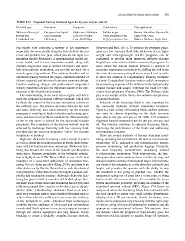
TABLE 17.2 Suggested fracture treatment types for dry gas, wet gas, and oil
Fracfluid type Formation Pump rate Conductivity Play application
Slickwater/linear gel Dry gas or low liquid High rates, 100 + bpm Infinite to gas Barnett, Marcellus, Fayetteville
Hybrid frac Gas condensate Low, 60–80 Bpm More conductive Frac Eagle Ford, Utica
Crosslinked frac Oil bearing Low, 40–60 Bpm Highly conductive frac Bakken, Niobrara, Eagle Ford
frac begins with collecting a number of key parameters (Brannon and Bell, 2011). To enhance the proppant place-
(especially the stress profile along the lateral) about the res- ment in a low viscosity fluid (like slickwater fracs), light-
ervoir and probable frac plan, which provide the input to a weight and ultra‐lightweight (ULW) proppants can be
fracturing model (Simulator). A geomechanical model, res- considered to provide more improved effective fracture
ervoir model, and fracture stimulation model, along with length than can be achieved with conventional proppants. In
multiple diagnostics such as surface tilt meters and down- cases where the natural fracture network is deemed of
hole microseismic monitoring, can provide the basis for a secondary importance to productivity, drilling the well in the
sound engineering solution. This solution should result in direction of minimum principal stress is preferred in order
optimized spacing between the stages, optimized number of to favor the creation of longitudinally trending hydraulic
clusters required, and the overall optimum treatment design. fractures. Longitudinal fractures reduce radial convergence
Fracture modeling, design, and posttreatment diagnostics by maximizing exposure of the wellbore to the hydraulically
(history matching) are also the important factors in the opti- created fracture and usually eliminate the need for high‐
mization of the stimulation treatment. conductivity proppants (Cramer, 2008). The Niobrara shale
The understanding of the local stress regime will deter- play is an example of this, that is, low numbers and presence
mine the optimum horizontal wellbore azimuth, which will of natural fractures.
facilitate the control of the fracture orientation relative to Selection of the fracturing fluids is very important for
the wellbore axis. The relative deviation between the well the successful hydraulic fracture stimulation treatment.
and stress field may also cause tortuosity (as the fracture There is a wide variety of fracturing fluids, and the optimum
propagates), resulting in higher initiation and treating pres- one must be chosen depending on the shale reservoir
sures, and lower near wellbore conductivity. The knowledge type, that is, dry gas, wet gas, or oil. Table 17.2 compares
of the in situ stress is critical for the successful fracture suggested fracture treatment types for dry gas, wet gas, and
placement. The complexity of the fracture network may be oil. The industry continues to optimize fracturing fluids,
achieved by multistage fracturing with low viscosity fluid, improving the performance of the fluids and addressing
provided that the reservoir properties “allow” the fracture environmental concerns.
complexity to develop. There are several methods of fracture treatment moni-
High‐rate slickwater fracturing creates tensile fractures toring, including but not limited to tilt meters, microseismic
as well as shears the existing fractures in brittle shale forma- monitoring, DTS, radioactive and nonradioactive tracers,
tions with low horizontal stress anisotropy. Slickwater frac- pressure monitoring, and production logging. Currently,
turing has become the norm in the Barnett and Marcellus the most frequently used/effective monitoring method
shale plays. Fracture complexity of the hydraulic stimula- is microseismic monitoring. With microseismic, the frac-
tion is highly desired. The Barnett Shale is one of the best turing operation can be monitored near real time by stage and
examples of a successful application of slickwater frac- changes made to existing or subsequent stages. Microseismic
turing. No two shales are alike (King, 2010), and there is no can monitor the treatment as to the direction (azimuth) and
other shale exactly like the Barnet that is, with the identical height, and provides the operator with the ability to stop
rock properties. Other shale reservoirs require a unique com- the treatment if not going as planned (i.e., whether the
pletion and stimulation strategy. Although slickwater frac- treatment is going out of zone, into a water zone, or being
turing has proved itself in a number of US shale plays, there lost to a fault, all in near real time). It can validate the stress
are many cases where slickwater fracturing has not provided profile and fracture geometry, providing an estimate of the
sufficient propped flow capacity to develop a gas or oil pro- stimulated reservoir volume (SRV). Figure 17.6 shows an
ductive shale. Unfortunately, slickwater fluid is an inher- analysis of where the fracturing fluids have interacted with
ently poor proppant carrier, necessitating high pump rates to the rock enough to create very small seismic disturbances
achieve flow velocities sufficient to overcome the tendency (displayed as a 3D microseismic cloud). As shown, seis-
of the proppants to settle. Advanced fluid technologies micity can be pinpointed very precisely with the right array
combine the best attributes of slickwater and conventional of sensors along with good interpretation expertise and the
cross‐linked fluids systems to maximize proppant transport appropriate representational software. Microseismic does
through the surface equipment and long laterals, before not indicate where the proppant or fluid actually goes, but
breaking to create a desirably complex fracture network where the rock has slipped or cracked. Some US operators