
Page 392 - Fundamentals of Gas Shale Reservoirs
P. 392
372 GAS SHALE CHALLENGES OVER THE ASSET LIFE CYCLE
X
Y
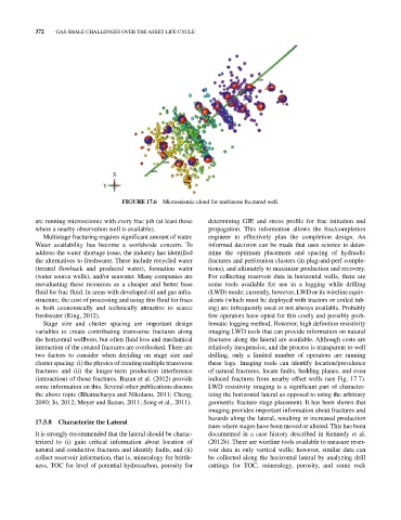
FIGURE 17.6 Microseismic cloud for multizone fractured well.
are running microseismic with every frac job (at least those determining GIP, and stress profile for frac initiation and
where a nearby observation well is available). propagation. This information allows the frac/completion
Multistage fracturing requires significant amount of water. engineer to effectively plan the completion design. An
Water availability has become a worldwide concern. To informed decision can be made that uses science to deter-
address the water shortage issue, the industry has identified mine the optimum placement and spacing of hydraulic
the alternatives to freshwater. These include recycled water fractures and perforation clusters (in plug‐and‐perf comple-
(treated flowback and produced water), formation water tions), and ultimately to maximize production and recovery.
(water source wells), and/or seawater. Many companies are For collecting reservoir data in horizontal wells, there are
reevaluating these resources as a cheaper and better base some tools available for use in a logging while drilling
fluid for frac fluid. In areas with developed oil and gas infra- (LWD) mode; currently, however, LWD or its wireline equiv-
structure, the cost of processing and using this fluid for fracs alents (which must be deployed with tractors or coiled tub-
is both economically and technically attractive to scarce ing) are infrequently used or not always available. Probably
freshwater (King, 2012). few operators have opted for this costly and possibly prob-
Stage size and cluster spacing are important design lematic logging method. However, high definition resistivity
variables to create contributing transverse fractures along imaging LWD tools that can provide information on natural
the horizontal wellbore, but often fluid loss and mechanical fractures along the lateral are available. Although costs are
interaction of the created fractures are overlooked. There are relatively inexpensive, and the process is transparent to well
two factors to consider when deciding on stage size and drilling, only a limited number of operators are running
cluster spacing: (i) the physics of creating multiple transverse these logs. Imaging tools can identify location/prevalence
fractures and (ii) the longer‐term production interference of natural fractures, locate faults, bedding planes, and even
(interaction) of those fractures. Bazan et al. (2012) provide induced fractures from nearby offset wells (see Fig. 17.7).
some information on this. Several other publications discuss LWD resistivity imaging is a significant part of character-
the above topic (Bhattacharya and Nikolaou, 2011; Cheng, izing the horizontal lateral as opposed to using the arbitrary
2010; Jo, 2012; Meyer and Bazan, 2011; Song et al., 2011). geometric fracture stage placement. It has been shown that
imaging provides important information about fractures and
hazards along the lateral, resulting in increased production
17.5.8 Characterize the Lateral
rates where stages have been moved or altered. This has been
It is strongly recommended that the lateral should be charac- documented in a case history described in Kennedy et al.
terized to (i) gain critical information about location of (2012b). There are wireline tools available to measure reser-
natural and conductive fractures and identify faults, and (ii) voir data in only vertical wells; however, similar data can
collect reservoir information, that is, mineralogy for brittle- be collected along the horizontal lateral by analyzing drill
ness, TOC for level of potential hydrocarbon, porosity for cuttings for TOC, mineralogy, porosity, and some rock