
Page 124 - Fundamentals of Light Microscopy and Electronic Imaging
P. 124
PHASE CONTRAST MICROSCOPY 107
Positive phase contrast Negative phase contrast
Phase plates
S P
P S
x
A D
A
x
D
D D
S S
P P
S S
P D
Advance the S-wave D Retard the S-wave
λ /4
λ /4 and reduce and reduce P
its amplitude S > P its amplitude P > S
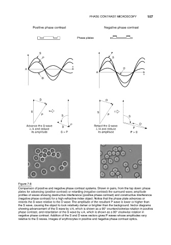
Figure 7-8
Comparison of positive and negative phase contrast systems. Shown in pairs, from the top down: phase
plates for advancing (positive contrast) or retarding (negative contrast) the surround wave; amplitude
profiles of waves showing destructive interference (positive phase contrast) and constructive interference
(negative phase contrast) for a high-refractive-index object. Notice that the phase plate advances or
retards the S wave relative to the D wave. The amplitude of the resultant P wave is lower or higher than
the S wave, causing the object to look relatively darker or brighter than the background. Vector diagrams
showing advancement of the S wave by /4, which is shown as a 90° counterclockwise rotation in positive
phase contrast, and retardation of the S wave by /4, which is shown as a 90° clockwise rotation in
negative phase contrast. Addition of the S and D wave vectors gives P waves whose amplitudes vary
relative to the S waves. Images of erythrocytes in positive and negative phase contrast optics.