
Page 122 - Fundamentals of Light Microscopy and Electronic Imaging
P. 122
PHASE CONTRAST MICROSCOPY 105
To differentially alter the phase and amplitude of the direct (undeviated) light, a
phase plate is mounted in or near the back focal plane of the objective (Figs. 7-6 and
7-7). In some phase contrast objectives, the phase plate is a plate of glass with an etched
ring of reduced thickness to selectively advance the phase of the S wave by /4. The
same ring is coated with a partially absorbing metal film to reduce the amplitude of the
light by 70–75%. In other lenses the same effect is accomplished by acid etching a lens
surface that is in or near the back focal plane of the objective lens. Regardless of the
method, it is important to remember that phase contrast objectives are always modified
in this way and thus are different from other microscope objectives.
The optical scheme for producing positive and negative phase contrast images is
given in Figure 7-8. As discussed in the preceding section, the D wave emergent from
the object plane is retarded by /4 relative to the phase of the S wave. In positive phase
contrast optics (left side of the diagram), the S wave is advanced in phase by /4 at the
phase plate, giving a net phase shift of /2, which now allows destructive interference
with D waves in the image plane. Generally, the manipulation of relative phase advance-
ment, while essential to phase contrast optics, is still unable to generate a high-contrast
image, because the amplitude of the S wave is too high to allow sufficient contrast. For
this reason, the ring in the phase plate is darkened with a semitransparent metallic coat-
ing to reduce the amplitude of the S wave by about 70%. Since P S D, interference
in the image plane generates a P wave with an amplitude that is now considerably less
than that of S. Thus, the difference in phase induced by the specimen is transformed into
a difference in amplitude (intensity). Since the eye interprets differences in intensity as
contrast (C
I/I ), we now see the object in the microscope. (See Chapter 2 for dis-
b
cussion of formula.) Positive phase contrast systems like the one just described differ-
entially advance the phase of the S wave relative to that of the D wave. Cellular objects
having a higher refractive index than the surrounding medium are dark in appearance,
whereas objects having a lower refractive index than the surrounding medium appear
bright.
λ
S( )
+
4
λ
( )
D – 4
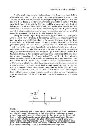
Figure 7-7
The action of a phase plate at the rear surface of the objective lens. Surround or background
rays (S) are advanced in phase relative to the D wave by /4 at the phase plate. Relative
phase advancement is created by etching a ring in the plate that reduces the physical path
taken by the S waves through the high-refractive-index plate. Since diffracted object rays (D)
are retarded by /4 at the specimen, the optical path difference between D and S waves
upon emergence from the phase plate is /2, allowing destructive interference in the image
plane. The recessed ring in the phase plate is made semitransparent so that the amplitude
of the S wave is reduced by 70–75% to optimize contrast in the image plane.