
Page 125 - Fundamentals of Light Microscopy and Electronic Imaging
P. 125
108 PHASE CONTRAST MICROSCOPY AND DARK-FIELD MICROSCOPY
(a) (b)
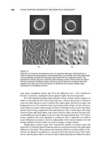
Figure 7-9
Alignment of condenser and objective annuli. An eyepiece telescope or Bertrand lens is
used to examine the back aperture of the objective lens. (a) The dark ring of the phase plate
must be perfectly centered with the bright ring of light from the condenser annulus. The
adjustment is made using two condenser plate-centering screws. These screws are distinct
from the condenser centration screws, which are used to center the condenser lens with
respect to the optic axis of the microscope. (b) Notice the low-contrast shaded image
resulting from a misaligned annulus.
large phase retardations (phase shift of the diffracted wave /2), interference
becomes constructive, making the objects appear brighter than the background.
To avoid confusion regarding bright and dark contrast in phase contrast images, it is
useful to reconsider the term optical path difference, which is the product of refractive
index and object thickness, and is related to the relative phase shift between object and
background waves. It is common to hear microscopists refer to high- and low-refractive-
index objects in a phase contrast image, but this is technically incorrect unless they know
that the objects being compared have the same thickness. Thus, a small object with a high
refractive index and a large object with a lower refractive index can show the same opti-
cal path difference and yet appear to the eye to have the same intensity (Fig. 7-10). In par-
ticular, conditions that cause shrinking or swelling of cells or organelles can result in
major differences in contrast. Likewise, replacement of the external medium with one
having a different refractive index can result in changes in image contrast.
Finally, phase contrast images show characteristic patterns of contrast—halos and
shade-off—in which the observed intensity does not correspond directly to the optical path
difference of the object. These patterns are sometimes referred to as phase artifacts or dis-
tortions, but should be recognized as a natural result of the optical system. Phase halos
always surround phase objects and may be dark or light depending on whether the optical