
Page 126 - Fundamentals of Light Microscopy and Electronic Imaging
P. 126
PHASE CONTRAST MICROSCOPY 109
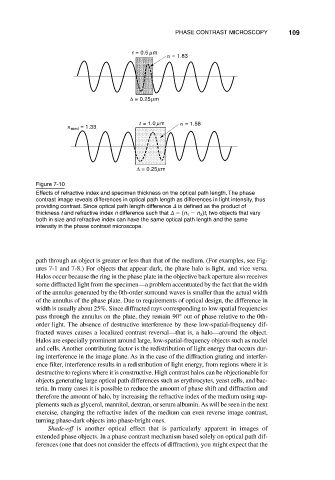
t = 0.5 µm
n = 1.83
∆ = 0.25µm
t = 1.0 µm n = 1.58
n med = 1.33
∆ = 0.25µm
Figure 7-10
Effects of refractive index and specimen thickness on the optical path length. The phase
contrast image reveals differences in optical path length as differences in light intensity, thus
providing contrast. Since optical path length difference
is defined as the product of
thickness t and refractive index n difference such that
(n n )t, two objects that vary
1
2
both in size and refractive index can have the same optical path length and the same
intensity in the phase contrast microscope.
path through an object is greater or less than that of the medium. (For examples, see Fig-
ures 7-1 and 7-8.) For objects that appear dark, the phase halo is light, and vice versa.
Halos occur because the ring in the phase plate in the objective back aperture also receives
some diffracted light from the specimen—a problem accentuated by the fact that the width
of the annulus generated by the 0th-order surround waves is smaller than the actual width
of the annulus of the phase plate. Due to requirements of optical design, the difference in
width is usually about 25%. Since diffracted rays corresponding to low spatial frequencies
pass through the annulus on the plate, they remain 90° out of phase relative to the 0th-
order light. The absence of destructive interference by these low-spatial-frequency dif-
fracted waves causes a localized contrast reversal—that is, a halo—around the object.
Halos are especially prominent around large, low-spatial-frequency objects such as nuclei
and cells. Another contributing factor is the redistribution of light energy that occurs dur-
ing interference in the image plane. As in the case of the diffraction grating and interfer-
ence filter, interference results in a redistribution of light energy, from regions where it is
destructive to regions where it is constructive. High contrast halos can be objectionable for
objects generating large optical path differences such as erythrocytes, yeast cells, and bac-
teria. In many cases it is possible to reduce the amount of phase shift and diffraction and
therefore the amount of halo, by increasing the refractive index of the medium using sup-
plements such as glycerol, mannitol, dextran, or serum albumin. As will be seen in the next
exercise, changing the refractive index of the medium can even reverse image contrast,
turning phase-dark objects into phase-bright ones.
Shade-off is another optical effect that is particularly apparent in images of
extended phase objects. In a phase contrast mechanism based solely on optical path dif-
ferences (one that does not consider the effects of diffraction), you might expect that the