
Page 177 - Fundamentals of Light Microscopy and Electronic Imaging
P. 177
160 DIC MICROSCOPY AND MODULATION CONTRAST MICROSCOPY
Blocked Blocked Transmitted
Analyzer
Resultant
waveform
Wollaston II
Phase
object
a b c
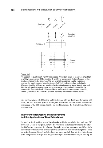
Figure 10-5
Progression of rays through the DIC microscope. An incident beam of linearly polarized light
is split by the condenser DIC prism into O- and E-ray components that are focused by the
condenser lens onto the specimen. The two rays follow separate parallel trajectories
between the condenser and objective lenses. (a, b) In the absence of an optical path
difference, the O and E rays are combined by the objective prism, giving linearly polarized
light that vibrates in the same plane as the polarizer and is completely blocked by the
analyzer. (c) If an optical path difference (phase shift) exists, the prism recombines the
beams, giving elliptically polarized light that is partially transmitted by the analyzer.
plus our knowledge of diffraction and interference tells us that image formation will
occur, but still does not provide a complete explanation for the unique shadow-cast
appearance of the DIC image. For this we need to examine the formation and behavior
of wavefronts.
Interference Between O and E Wavefronts
and the Application of Bias Retardation
As just described, incident rays of linearly polarized light are split by the condenser DIC
prism into O- and E-ray pairs, traverse the specimen, and are recombined by the objec-
tive DIC prism, generating linearly and elliptically polarized waves that are differentially
transmitted by the analyzer according to the azimuths of their vibrational planes. Since
transmitted rays are linearly polarized and are plane parallel, they interfere in the image
plane and generate an amplitude image of the object. Another useful way of viewing the