
Page 181 - Fundamentals of Light Microscopy and Electronic Imaging
P. 181
164 DIC MICROSCOPY AND MODULATION CONTRAST MICROSCOPY
(a) (b) (c)
(d) (e) (f) (g)
(h) (i)
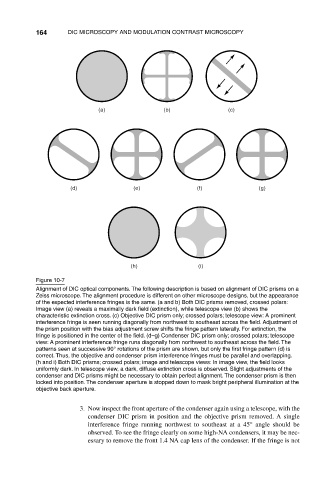
Figure 10-7
Alignment of DIC optical components. The following description is based on alignment of DIC prisms on a
Zeiss microscope. The alignment procedure is different on other microscope designs, but the appearance
of the expected interference fringes is the same. (a and b) Both DIC prisms removed, crossed polars:
Image view (a) reveals a maximally dark field (extinction), while telescope view (b) shows the
characteristic extinction cross. (c) Objective DIC prism only; crossed polars; telescope view: A prominent
interference fringe is seen running diagonally from northwest to southeast across the field. Adjustment of
the prism position with the bias adjustment screw shifts the fringe pattern laterally. For extinction, the
fringe is positioned in the center of the field. (d–g) Condenser DIC prism only; crossed polars; telescope
view: A prominent interference fringe runs diagonally from northwest to southeast across the field. The
patterns seen at successive 90° rotations of the prism are shown, but only the first fringe pattern (d) is
correct. Thus, the objective and condenser prism interference fringes must be parallel and overlapping.
(h and i) Both DIC prisms; crossed polars; image and telescope views: In image view, the field looks
uniformly dark. In telescope view, a dark, diffuse extinction cross is observed. Slight adjustments of the
condenser and DIC prisms might be necessary to obtain perfect alignment. The condenser prism is then
locked into position. The condenser aperture is stopped down to mask bright peripheral illumination at the
objective back aperture.
3. Now inspect the front aperture of the condenser again using a telescope, with the
condenser DIC prism in position and the objective prism removed. A single
interference fringe running northwest to southeast at a 45° angle should be
observed. To see the fringe clearly on some high-NA condensers, it may be nec-
essary to remove the front 1.4 NA cap lens of the condenser. If the fringe is not