
Page 180 - Fundamentals of Light Microscopy and Electronic Imaging
P. 180
THE DIC OPTICAL SYSTEM 163
scratches, lint, bubbles, and dirty lens surfaces. Adjustments of DIC optical components
are critical to imaging performance, so it is important to recognize misalignments and
faults and correct them if necessary. The appearance of the image at different steps of
alignment is shown in Figure 10-7, and the operation is performed as follows:
1. Cross the polarizer and analyzer. The polarizer (near the light source) is oriented
in an east-west direction as you face the microscope. A mark on the mounting
ring of the polarizer indicates its transmission axis. Before adjusting the ana-
lyzer, remove all optical components, including the condenser, the objective
lens, and DIC prisms. When the analyzer is crossed at 90° with respect to the
polarizer, the field looks maximally dark (extinction) when observed through the
eyepieces. If the field of view is not dark, move the analyzer in its mounting until
the transmission axis is oriented in a north-south direction. If the analyzer is
fixed and the polarizer is rotatable, this adjustment is made in the reverse order.
When the objective and condenser are inserted (but without the DIC prisms) and
the microscope is focused on a blank slide and adjusted for Koehler illumina-
tion, the field looks dark in visual mode and a dark extinction cross can be seen
in the back aperture of the objective lens with an eyepiece telescope or Bertrand
lens. If the polarizer and analyzer are mounted properly, the extinction cross will
have straight horizontal and vertical components. There should not be any bright
birefringent streaks, which are indicators of strained lenses and inferior per-
formance in DIC.
2. Examine the objective back aperture, with the objective DIC prism in position
and the condenser prism removed. A single dark interference fringe extends
across the diameter of the back aperture from the northwest to southeast quad-
rants at a 45° angle. The fringe should be well defined and should run through
the middle of the aperture. The objective prism is fixed in some microscope
designs, but in others it can be adjusted using a prism positioning screw. The
image field as seen through the eyepieces looks bright and featureless.
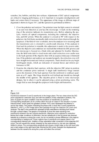
Figure 10-6
Interference between O and E wavefronts in the image plane. The two views show the DIC
prism adjusted for extinction (top) and with the addition of bias retardation (bottom). The
pairs of graphs for each condition show the positions of wavefronts ( ) and the
corresponding amplitudes (A) for profiles taken through an object in the direction of prism-
induced shear, which gives the greatest contrast. The x-axis represents the distance x
across the object. The graphs indicating the phase shift show the O and E wavefronts
(labeled and ) in the image plane after passage through the objective DIC prism and
1
2
analyzer. The dips in the wavefronts represent phase retardations resulting from transit
through a phase object. The graphs of amplitude A show the wave resulting from
interference between the two original wavefronts. Objective prism adjusted to extinction:
Notice that under conditions of extinction, the two wavefronts in the top panel are sheared
laterally by a distance a along the x-axis, but do not exhibit a phase difference in the regions
corresponding to background. These regions have 0 amplitude and appear black in the
corresponding intensity plot. Addition of bias retardation after movement of the objective DIC
prism: The two wavefronts remain sheared by the same amount a, but are now relatively
shifted in phase. The corresponding amplitude plot shows a bright edge on the left-hand side
and a dark edge on the right-hand side. Moving the DIC prism changes the displacement
between the two wavefronts along the y-axis and alters the contrast.