
Page 210 - Fundamentals of Light Microscopy and Electronic Imaging
P. 210
ARRANGEMENT OF FILTERS AND THE EPI-ILLUMINATOR 193
100
80
Relative intensity 60 Excitation Emission
40
20
0
300 350 400 450 500 550 600 650 700
Wavelength (nm)
(a)
100
80 Exciter filter
% Transmission 60 Dichroic mirror Barrier filter
40
20
0
300 350 400 450 500 550 600 650 700
Wavelength (nm)
(b)
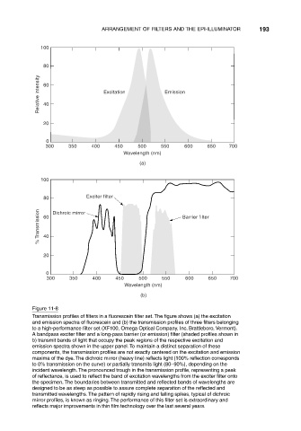
Figure 11-8
Transmission profiles of filters in a fluorescein filter set. The figure shows (a) the excitation
and emission spectra of fluorescein and (b) the transmission profiles of three filters belonging
to a high-performance filter set (XF100, Omega Optical Company, Inc. Brattleboro, Vermont).
A bandpass exciter filter and a long-pass barrier (or emission) filter (shaded profiles shown in
b) transmit bands of light that occupy the peak regions of the respective excitation and
emission spectra shown in the upper panel. To maintain a distinct separation of these
components, the transmission profiles are not exactly centered on the excitation and emission
maxima of the dye. The dichroic mirror (heavy line) reflects light (100% reflection corresponds
to 0% transmission on the curve) or partially transmits light (80–90%), depending on the
incident wavelength. The pronounced trough in the transmission profile, representing a peak
of reflectance, is used to reflect the band of excitation wavelengths from the exciter filter onto
the specimen. The boundaries between transmitted and reflected bands of wavelengths are
designed to be as steep as possible to assure complete separation of the reflected and
transmitted wavelengths. The pattern of rapidly rising and falling spikes, typical of dichroic
mirror profiles, is known as ringing. The performance of this filter set is extraordinary and
reflects major improvements in thin film technology over the last several years.