
Page 171 - Fundamentals of Magnetic Thermonuclear Reactor Design
P. 171
152 Fundamentals of Magnetic Thermonuclear Reactor Design
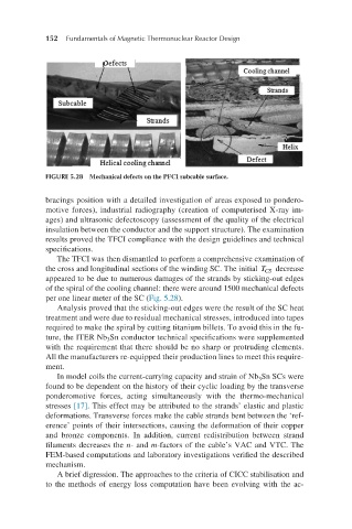
FIGURE 5.28 Mechanical defects on the PFCI subcable surface.
bracings position with a detailed investigation of areas exposed to pondero-
motive forces), industrial radiography (creation of computerised X-ray im-
ages) and ultrasonic defectoscopy (assessment of the quality of the electrical
insulation between the conductor and the support structure). The examination
results proved the TFCI compliance with the design guidelines and technical
specifications.
The TFCI was then dismantled to perform a comprehensive examination of
TCS the cross and longitudinal sections of the winding SC. The initial T decrease
CS
appeared to be due to numerous damages of the strands by sticking-out edges
of the spiral of the cooling channel: there were around 1500 mechanical defects
per one linear meter of the SC (Fig. 5.28).
Analysis proved that the sticking-out edges were the result of the SC heat
treatment and were due to residual mechanical stresses, introduced into tapes
required to make the spiral by cutting titanium billets. To avoid this in the fu-
ture, the ITER Nb Sn conductor technical specifications were supplemented
3
with the requirement that there should be no sharp or protruding elements.
All the manufacturers re-equipped their production lines to meet this require-
ment.
In model coils the current-carrying capacity and strain of Nb Sn SCs were
3
found to be dependent on the history of their cyclic loading by the transverse
ponderomotive forces, acting simultaneously with the thermo-mechanical
stresses [17]. This effect may be attributed to the strands’ elastic and plastic
deformations. Transverse forces make the cable strands bent between the ‘ref-
erence’ points of their intersections, causing the deformation of their copper
and bronze components. In addition, current redistribution between strand
filaments decreases the n- and m-factors of the cable’s VAC and VTC. The
FEM-based computations and laboratory investigations verified the described
mechanism.
A brief digression. The approaches to the criteria of CICC stabilisation and
to the methods of energy loss computation have been evolving with the ac-