
Page 170 - Fundamentals of Magnetic Thermonuclear Reactor Design
P. 170
Superconducting Magnet Systems Chapter | 5 151
pure titanium jackets and 0.5% for SCs using 316LN austenitic stainless-steel
jackets. These materials were used to jacket the SC cables of model coils, with
Incoloy being a material of choice for the CSMC, titanium for the TFCI, and
stainless steel for TFMC. Test results disclose the inadequacy of the linear
elasticity model for assessing the relative strain of the Nb Sn strands in cable
3
twists, and the ambiguity of the ‘advantages,’ the complexity of the techniques
and the increased risk of Incoloy’s and titanium’s practical application in the
MC of ITER scale. As a result, only 316LN stainless steel was chosen and
included in the ITER design specifications as a jacket material of the TFC and
CS conductors.
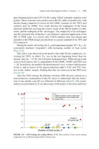
During the model coil testing, the T and temperature margin T∆= T CS − T ∆T=TCS−T 0
0
CS
consistently declined (‘degraded’) with increasing number of load cycles
(Fig. 5.27).
This effect was observed in all model coils with Nb Sn conductors, ex-
3
cluding the TFCI, in which T was at the test beginning lower than the TCS
CS
design value by ∼1.5 K, but remained unchanged later. When design loads
were at their highest, the T degradation in the CSMC, TFMC and CSCI was
CS
∼1 K. In addition, the model coils demonstrated a two- to three-fold decrease
in the n- and m-factors of the superconducting cable’s VAC and VTC rela-
tive to the ‘initial’ strands. Nothing like that was observed in the TFCI tests
[11,14,15].
After the TFCI testing, the Efremov Institute (SPb, Russia) carried out a
non-destructive examination of this SС insert to understand why the behav-
iour of one and the same SC was different for different coils [16]. The exami-
nation was performed by X-ray introscopy (with respect to the turns and force
FIGURE 5.27 CSCI testing, the cycling (40 kA; 13 T). The evolution of the current sharing
temperature (T CS ) with increasing number of load cycles .