
Page 169 - Fundamentals of Magnetic Thermonuclear Reactor Design
P. 169
150 Fundamentals of Magnetic Thermonuclear Reactor Design
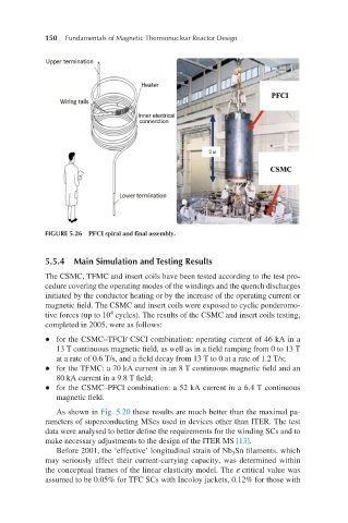
FIGURE 5.26 PFCI spiral and final assembly.
5.5.4 Main Simulation and Testing Results
The CSMC, TFMC and insert coils have been tested according to the test pro-
cedure covering the operating modes of the windings and the quench discharges
initiated by the conductor heating or by the increase of the operating current or
magnetic field. The CSMC and insert coils were exposed to cyclic ponderomo-
4
tive forces (up to 10 cycles). The results of the CSMC and insert coils testing,
completed in 2005, were as follows:
l for the CSMC–TFCI/ CSCI combination: operating current of 46 kA in a
13 T continuous magnetic field, as well as in a field ramping from 0 to 13 T
at a rate of 0.6 T/s, and a field decay from 13 T to 0 at a rate of 1.2 T/s;
l for the TFMC: a 70 kA current in an 8 T continuous magnetic field and an
80 kA current in a 9.8 T field;
l for the CSMC–PFCI combination: a 52 kA current in a 6.4 T continuous
magnetic field.
As shown in Fig. 5.20 these results are much better than the maximal pa-
rameters of superconducting MSes used in devices other than ITER. The test
data were analysed to better define the requirements for the winding SCs and to
make necessary adjustments to the design of the ITER MS [13].
Before 2001, the ‘effective’ longitudinal strain of Nb Sn filaments, which
3
may seriously affect their current-carrying capacity, was determined within
the conceptual frames of the linear elasticity model. The ε critical value was
assumed to be 0.05% for TFC SCs with Incoloy jackets, 0.12% for those with